주요 콘텐츠로 건너뛰기

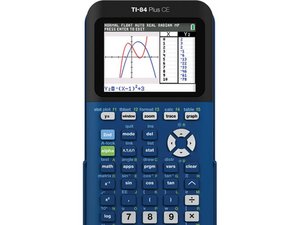
The TI-84 Plus CE is a graphing calculator released in Spring 2015 by Texas Instruments. It includes a 2.8 inch color screen, USB port, apps, storage, and a 1200 mAh battery.

82 질문 전체 보기

TI-84 Plus CE - ON Button Not Working To Turn On or Off

The ON keypad button does nothing, but everything else works fine. I can only turn on the calculator in 3 ways:

  1. Remove and reinsert the battery which also clears the RAM.
  2. Press the tiny reset button in the back which also clears the RAM.
  3. Plug in the charging cable while connected to a charger which does not clear the RAM.

When it’s on, I can’t turn it off. Pressing 2nd - ON does nothing. If I leave it alone, it will power off after about 3 minutes of idle time when unplugged and about 15 minutes when connected to a charger. When it's off, pressing the ON button does nothing and I have to use one of the 3 methods above to turn it back on.

I tried everything in "TI-84 Plus CE Recovery Techniques" including reinstalling the OS, but the problem is exactly the same which leads me to believe it’s a hardware problem, so I disassembled it and removed the PCB board, finding some traces of corrosion on the PCB board by the ON switch contact and on the rubber actuator. I cleaned them with alcohol and reinstalled the OS again just in case. I also installed a brand new battery, but after all of that, the symptoms are the same. Any ideas about how to fix this would be greatly appreciated.

Update (03/03/2021)

Block Image

Block Image

Block Image

이 질문에 답하기 저도 같은 문제를 겪고 있습니다

좋은 질문 입니까?

점수 1
댓글 달기

답변 1개

가장 유용한 답변

Thank you for providing all that information! As you guessed, this is definitely a hardware issue. Could you please provide an image of the corrosion (be sure to check if the corrosion is on both sides of the board)? I can see if there’s enough contact left for you to solder jumper wires in place of the traces.

In the meantime, if you have the mini-USB to mini-USB cable the came with the calculator, you can plug side A (the white side) into the calculator and it will turn on. This is similar to plugging the calculator into the charger but this method does not need a power source and also doesn’t clear the RAM.

EDIT:

Alright, I got some help from NoahK. I know you said you checked continuity, but I'll relay that info again. So, the round contacts you see around the button are call test points.

  • The test point at the top should be continuous with the circle in the middle.
  • The test point to the top right should be continuous with the ‘floating’ triangles.
  • The test point to the bottom left is ground and should be continuous with the outer ring.
  • None of the test points should be continuous with eachother

I know this may be hard to understand through text, so I made a quick color coded picture to explain it:

Block Image

Shorting the two non-ground pins (the yellow and dark blue in the photo) will turn on the calculator.

Unfortunately, the ON button is special and isn’t connected to the rest of the key matrix so you can’t just connect the button to other keys. I don’t have the info to where exactly the ON button connects to yet.

해당 답변은 도움이 되었습니까?

점수 1

댓글 9개:

I only took before pictures, but after cleaning up with a bit of alcohol, it looked like new. I even checked continuity with a multimeter. I’m sure it’s something bad on the board, but have no idea what it would be or if it’s even possible to replace.

In the meantime, I don’t have that cable, but just ordered one from eBay.

Thanks for the photos! It looks like you could solder jumper wires, but I'll have to get back to you on where exactly you would need to put them.

@bcassidy I know you said you already checked continuity, but I've added details about it to the answer. I'm still working on getting info on where the traces actually go to.

You guys are amazing. I had no idea you could test the continuity that way, so took it back apart and all of those checks were OK except between the lower left and upper right test points. It seems they are connected across a capacitor, because when I use an ohm-meter, I get about 300K-ohms that drops to about 60K-ohms. When I reverse the leads, the same thing happens. I also took another picture.

TheLastMillennial, would you please tell me how you made that diagram? What program did you use. That's awesome.

댓글 4개 더보기

댓글 달기

귀하의 답변을 추가하세요

Bob Cassidy 님은 대단히 고마워 할 것입니다.
조회 통계:

24 시간 전: 4

7일 전: 24

30일 전: 117

전체 시간: 2,273