주요 콘텐츠로 건너뛰기

이 버전에는 잘못된 편집 사항이 있을 수 있습니다. 최신 확인된 스냅샷으로 전환하십시오.

필요한 것

  1. 이 단계는 번역되지 않았습니다. 번역을 도와주십시오

    : 1 단계, 이미지 1/2 : 1 단계, 이미지 2/2
    • Remove the following screws:

    • Two silver 3.15mm Phillips #00 screws on the right side of the camera

    • Two silver 2.08mm Phillips #00 screws on the left side of the camera

  2. 이 단계는 번역되지 않았습니다. 번역을 도와주십시오

    : 2 단계, 이미지 1/1
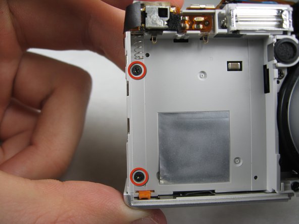
    • Remove the two indicated screws on the bottom of the camera:

    • The screw circled in red is a longer silver 3.15mm Phillips #00 screw

    • The screw circled in blue is a shorter silver 2.25mm Phillips #00 screw

  3. 이 단계는 번역되지 않았습니다. 번역을 도와주십시오

    : 3 단계, 이미지 1/2 : 3 단계, 이미지 2/2
    • Carefully pull the back of casing away from the front.

  4. 이 단계는 번역되지 않았습니다. 번역을 도와주십시오

    : 4 단계, 이미지 1/3 : 4 단계, 이미지 2/3 : 4 단계, 이미지 3/3
    • After removing the back cover, several things must be removed.

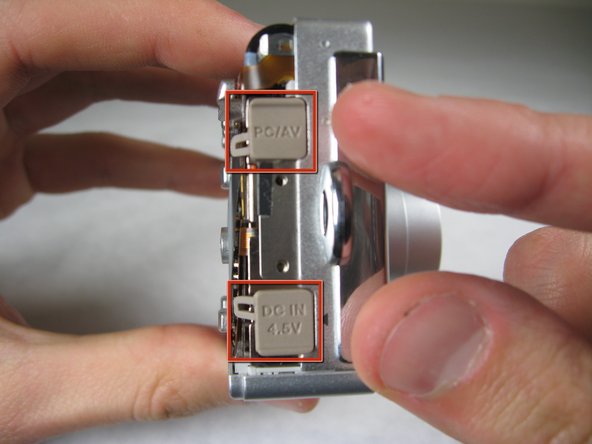
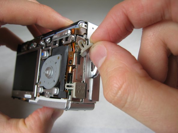
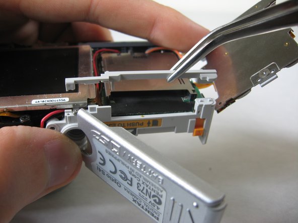
    • Silver donut-shaped button will fall off. Place separately. Remove the plug covers on the right side of camera, labeled “PC/AV” and “DC IN 4.5V”.

  5. 이 단계는 번역되지 않았습니다. 번역을 도와주십시오

    : 5 단계, 이미지 1/2 : 5 단계, 이미지 2/2
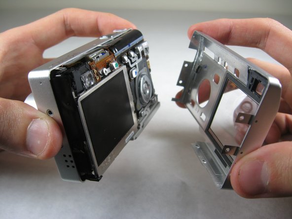
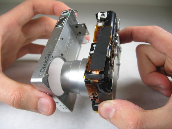
    • To remove the front cover, gently hold the inside structure of the camera and slowly pull the front cover off.

  6. 이 단계는 번역되지 않았습니다. 번역을 도와주십시오

    : 6 단계, 이미지 1/2 : 6 단계, 이미지 2/2
    • On the front of the camera, in battery case, remove screws indicated:

    • Two black 2.05mm Phillips #00 screws

  7. 이 단계는 번역되지 않았습니다. 번역을 도와주십시오

    : 7 단계, 이미지 1/2 : 7 단계, 이미지 2/2
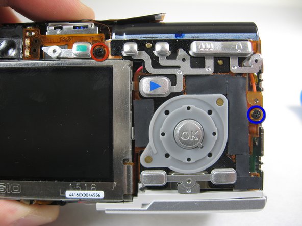
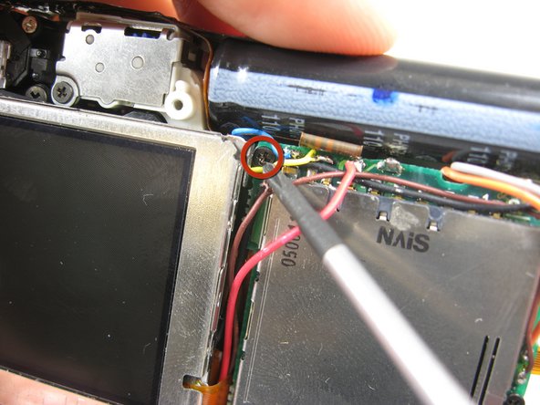
    • Flip the camera over to the backside and remove screws indicated:

    • The screw circled in red is a longer black 3.00mm Phillips #00 screw

    • The screw circled in blue is a shorter black 2.00mm Phillips #00 screw

  8. 이 단계는 번역되지 않았습니다. 번역을 도와주십시오

    : 8 단계, 이미지 1/1
    • Pull the cover plate off for the two power cord jacks.

  9. 이 단계는 번역되지 않았습니다. 번역을 도와주십시오

    : 9 단계, 이미지 1/3 : 9 단계, 이미지 2/3 : 9 단계, 이미지 3/3
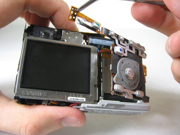
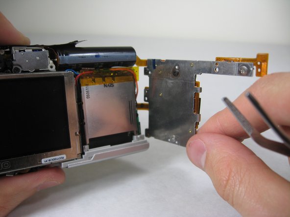
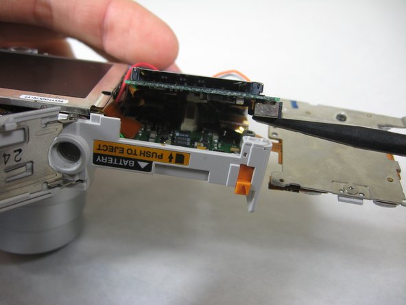
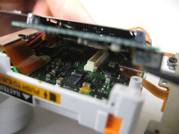
    • Cautiously and gently pull up the control board at the upper left corner, next to the viewfinder.

  10. 이 단계는 번역되지 않았습니다. 번역을 도와주십시오

    : 10 단계, 이미지 1/1
    • Remove the orange tape on top of the SD cardholder.

  11. 이 단계는 번역되지 않았습니다. 번역을 도와주십시오

    : 11 단계, 이미지 1/1
    • Open the battery cover.

  12. 이 단계는 번역되지 않았습니다. 번역을 도와주십시오

    : 12 단계, 이미지 1/2 : 12 단계, 이미지 2/2
    • Lift the indicated plastic piece off.

  13. 이 단계는 번역되지 않았습니다. 번역을 도와주십시오

    : 13 단계, 이미지 1/2 : 13 단계, 이미지 2/2
    • Remove screws indicated:

    • Two black 4.80mm Phillips #00 screws

  14. 이 단계는 번역되지 않았습니다. 번역을 도와주십시오

    : 14 단계, 이미지 1/1
    • Unsolder points indicated.

    • Please refer to steps 1 through 6 of the Ifixit soldering guide to unsolder these leads.

  15. 이 단계는 번역되지 않았습니다. 번역을 도와주십시오

    : 15 단계, 이미지 1/3 : 15 단계, 이미지 2/3 : 15 단계, 이미지 3/3
    • Carefully lift up SD cardholder to reveal logicboard.

결승점

Nicole Wong

회원 가입일: 01/30/11

329 평판

안내서 3개 작성하였습니다

Cal Poly, Team 4-29, Regan Winter 2011 Cal Poly, Team 4-29, Regan Winter 2011 회원

CPSU-REGAN-W11S4G29

3 회원들

안내서 10개 작성하였습니다

댓글 0개

댓글 쓰기

조회 통계:

24 시간 전: 0

7일 전: 0

30일 전: 0

전체 시간: 1,380