이 안내서에는 최근 변경 사항이 더 있습니다. 최신 비검증 버전으로 전환하십시오.
소개
If your AL2216W is having problems, it is likely a capacitor fault. Here are some signs of bad capacitors:
Note: While some issues may be corrected with a partial repair, this is not recommended as the untouched capacitors will eventually fail.
- Power issues (Present issue)
- Excessive transformer hum (Present issue)
- Excessive inverter hum (Present issue)
- Troublesome VGA Auto adjust (Present issue)
- Backlight problems
- Power problems
- Video issues (Ex: Unstable image, PC connection issues, unreliable at higher resolutions)
- Random power issues that may only resolve if the monitor is physically unplugged.
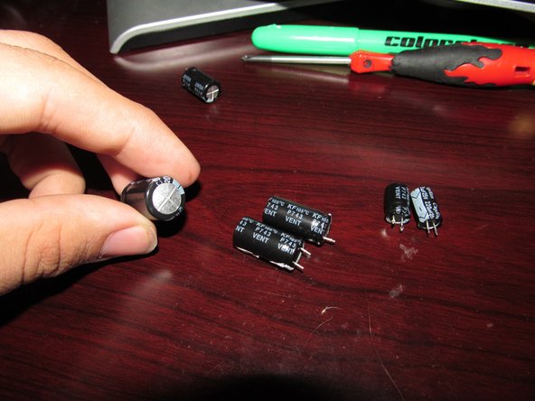
Original capacitor values (Primarily reference only)
NOTE: Most of these values are obsolete. Many will need to be substituted with modern replacements when they fail, so this is primarily included for reference purposes.
- 25V 1000uF (x2)
- 10V 1000uF (x1)
- 25V 220uF (x2)
- 16V 2200uF (Early power supplies)
필요한 것
-
-
Unplug the monitor and leave it unplugged for 24-48 hours. Wait 5-7 days if you intend to replace the filter capacitor.
-
-
-
Remove the stand from the monitor. Remove the 4 screws that hold the stand on. The bottom screws should be removed first, but this can be done in any order.
-
-
-
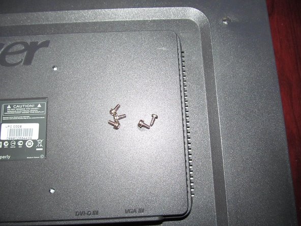
Remove 4 fine threaded screws from the back of the monitor. All of these screws are the same type and length.
-
This screw is unique and only goes in one place as the thread is different. Set it aside separately from the other screws.
-
-
-
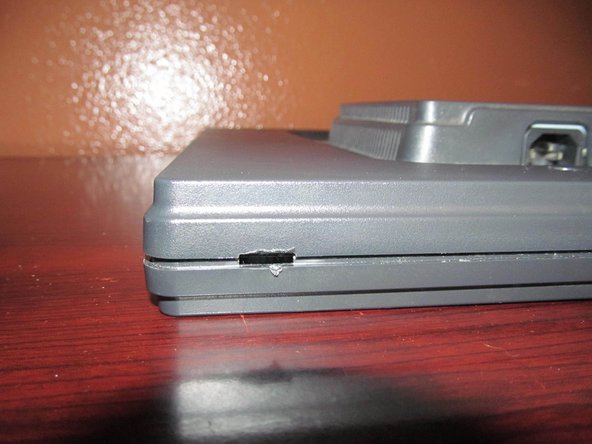
On the bottom of the monitor, there are four slots to open the monitor. To release these clips, use a Jimmy or flathead screwdriver.
-
-
-
With the monitor unclipped on the bottom, pull the sides of the monitor up. Do this slowly to avoid damaging the plastics and LCD.
-
-
-
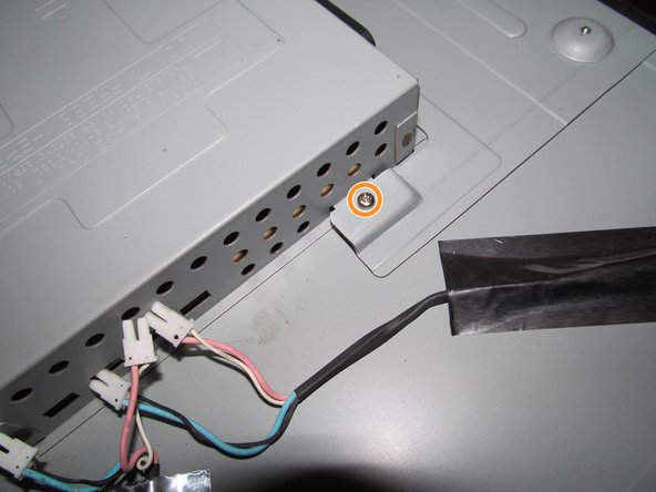
With the back of the monitor off, remove the 2 screws on the IEC power connector.
-
-
-
Remove the 4 screw pins for the video cables from the monitor. Use a 5mm Nut bit/driver to remove the screw pins from the power supply shield.
-
-
-
-
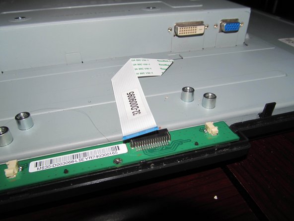
Disconnect the flat flex cable that goes to the control board.
-
-
-
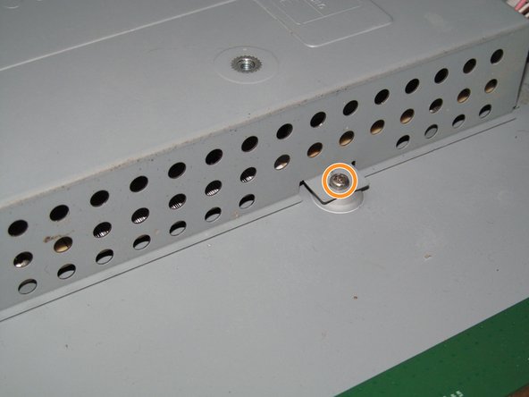
Remove the 2 bottom screws that hold the power supply shield to the monitor.
-
-
-
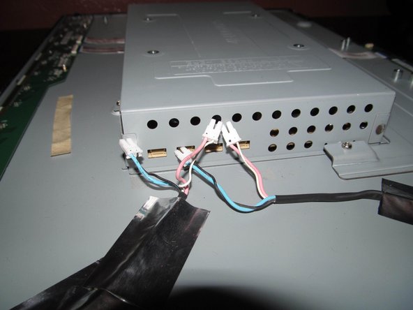
On the right side of the monitor, remove the remaining screws holding the upper shield in place.
-
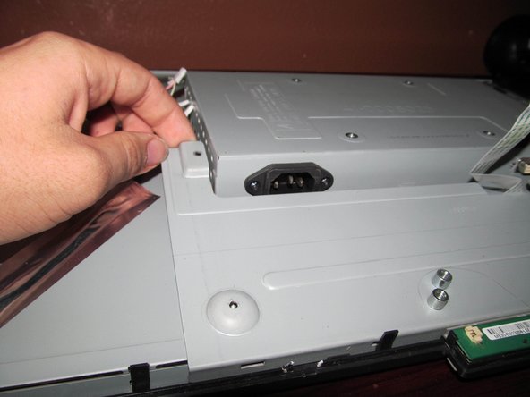
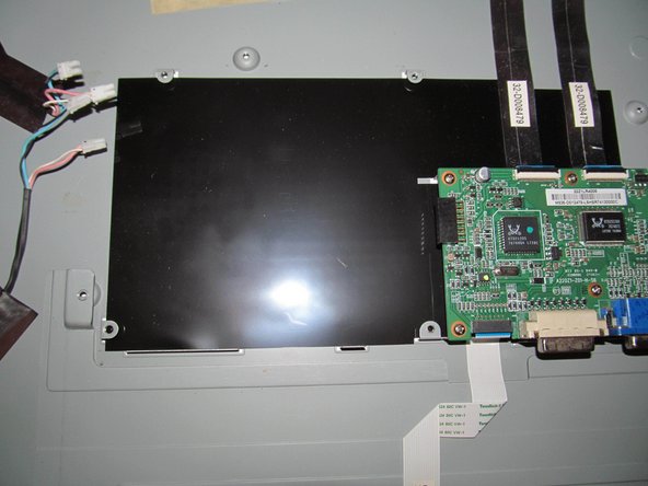
Lift the lower plate up while removing the power supply shield to remove it from the monitor. Once this is done, you will have access to the power supply.
-
-
-
This capacitor is only used on older revisions. If your board has this capacitor, it should be replaced if handy.
-
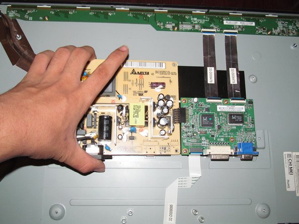
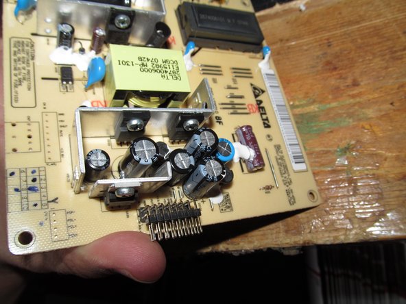
With the power supply shield removed from the monitor, identify the power supply. Along with the listed capacitors, take note of any others you want to replace (Ex: Inverter coil).
-
Remove the 4 screws from the power supply. Once this is done, lift up the power supply at a slight angle to clear the chassis mounting holes.
-
-
-
If you are unsure of the position of the capacitors, mark the polarity with a permanent marker. If the capacitors are installed incorrectly, they will explode when power is applied.
-
-
-
To prepare the board for capacitor replacement, add flux or solder to ease removal.
-
-
-
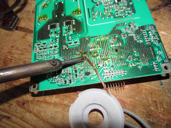
Move in a workspace with ventilation or use a fume extractor. Once in an appropriate workspace, desolder the old capacitors. Heat up the leg to remove it from the board.
-
After removing the capacitors, clean up the old solder with a desoldering braid Lift it with the iron when removing it.
-
-
-
Install the new capacitors. Check the polarity/placement and bend the leads so they do not come loose during installation.
-
-
-
Once the polarity is verified, solder the capacitors in. After installation, cut off any excess lead.
-
-
-
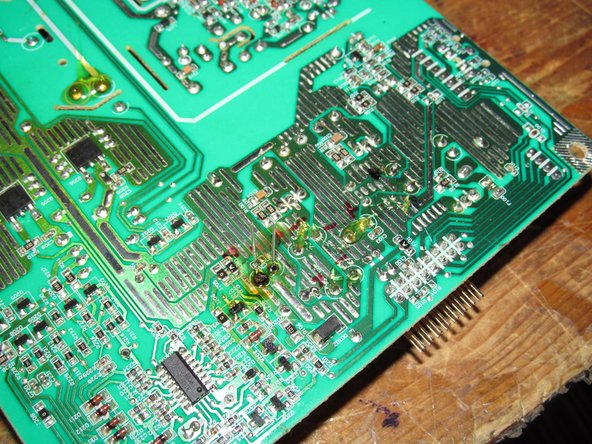
After verifying there are no cold solder joints, clean the board. This can be cleaned with 91%+ Isopropyl or Denatured alcohol.
-
-
-
Put the monitor back together and test it with a signal. If the repair worked, you will have a visible image.
-


To reassemble your device, follow these instructions in reverse order.
To reassemble your device, follow these instructions in reverse order.
다른 12명이 해당 안내서를 완성하였습니다.

팀

댓글 28개
I did not replace the large capacitor on the Acer monitor yet. All other caps have been replaced. I may have to replace the FSPO55- ZP102A as it has a hot spot beside it. I don't know if the part number is right? Do know where I can buy it. Tom B
These older CCFL panels usually burn on the PCB by the inverter coil and main transformer (the Delta branded part, in this case). The LED monitors limit the failure points to the transformer.
It sounds like your PCB got burned from the heat by the transformer or the inverter coil. This is very common and the boards are designed to take it. However, if you are concerned you should buy a new power supply board altogether if that makes you more comfortable.
Nick -
In step 12, replacing the capacitors with ones with a different capacitance rating instead of using a capacitor rated for higher voltage makes no sense to me electrically. The capacitance rating is the important part, if you use a capacator rated for say 35 volts when the original is rated for 10 makes no difference whatsoever. the rating just means MAX voltage.