소개
A DLP projector creates the image using a digital micromirror device (DMD). This contains one micromirror per pixel, each of which can be individually deflected electrically in order to reflect light from the lamp either through the lens and on to the screen, or into a light sump where it is absorbed. The DMD is essentially a monochrome device and so a rapidly spinning colour wheel is placed in front of the lamp. This passes each of the three primary colours in turn, so allowing the colour image to be built up from the red, green and blue components projected one after the other.
A faulty colour wheel is indicated in this projector by the Lamp indicator LED on the control panel flashing, but can also be indicated by the image flickering different colours. A replacement colour wheel is quite easily fitted.
필요한 것
-
-
Release the top cover with a spudger inserted along the front edge. Lift it off from the front.
-
-
-
Remove the transparent film over the lamp, and put it aside.
-
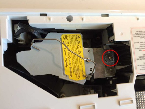
Lift the lamp handle. Undo the captive screw which secures the lamp. Disconnect the lamp power connector and lift out the lamp.
-
-
-
Remove a screw from just in front of the control buttons.
-
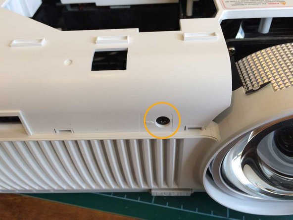
Remove a screw from the front just to the left of the lens.
-
Turn the projector over and remove 5 recessed screws from the holes with arrows against them.
-
-
-
Release the top cover by running a spudger around all 4 sides. Remove the cover.
-
-
-
-
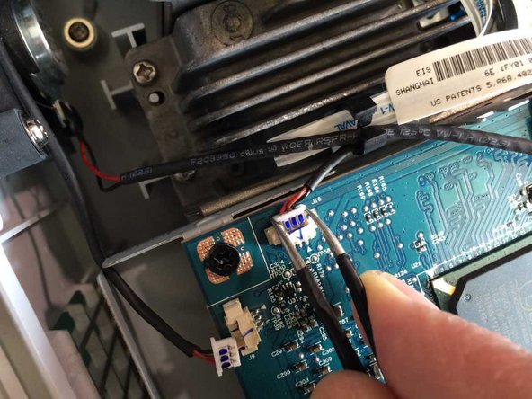
Disconnect 6 connectors. Do not pull them out by the wires as the wires may come out of the plugs. Instead, ease them out with a pair of tweezers as shown, or with a thumbnail on each side.
-
Gently pull the ribbon cable out of its socket.
-
-
-
Remove 4 screws securing the main board.
-
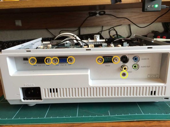
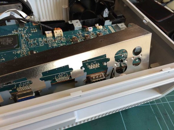
Remove 6 binding posts on the VGA and serial sockets with a 3/16in or 5mm socket or spanner, a small adjustable spanner, or if you have none of those, a pair of pliers.
-
Remove a screw from below the phono video socket.
-
Angle the rear panel backwards in order to remove it. Remove also the metal screen.
-
-
-
Gently lift the main board off the optical assembly and power supply connectors, and put it aside.
-
-
-
A long magnetic screwdriver is very helpful for this step, and almost essential for reassembly.
-
Remove a screw and toothed lock washer from the rear left of the metal plate.
-
Remove a screw from the rear right of the metal plate.
-
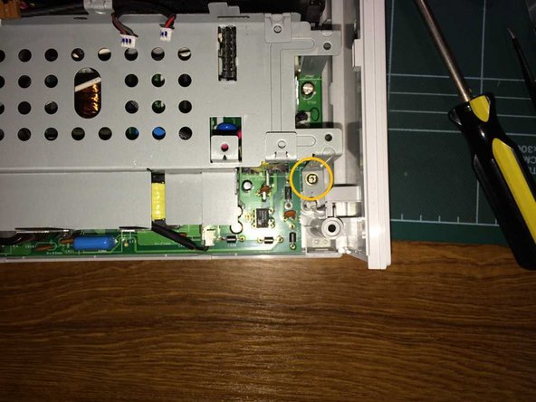
Remove a screw from the front right of the metal plate.
-
-
-
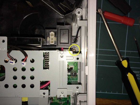
Remove a black screw from the front of the metal plate engaging with the optical assembly. This may be hidden by the wires passing through the adjacent wire clip.
-
Lift out the metal plate.
-
-
-
Remove the front panel by releasing 3 clips along the bottom, using a spudger, then angling it forwards.
-
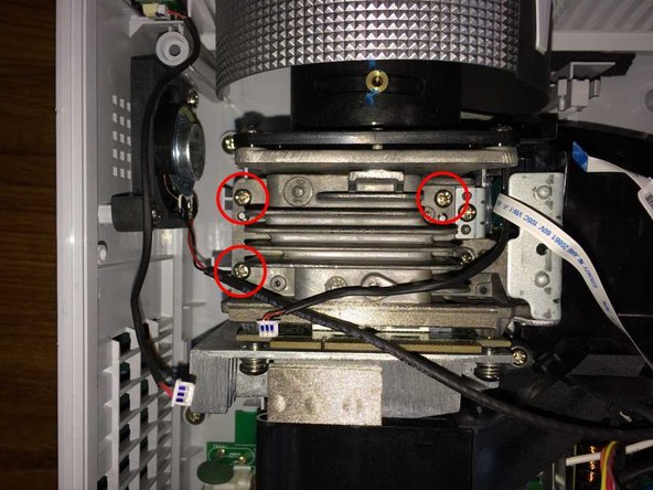
Remove 3 screws on the top of the optical assembly. On the right, do not remove the adjacent screw securing the colour wheel assembly.
-
Lift out the complete optical assembly.
-
-
-
Remove 2 screws on the side of the colour wheel guard and remove the guard.
-
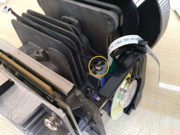
Remove a screw above and behind the colour wheel, and remove the wheel assembly.
-
-
-
Disconnect the rotary position sensor cable.
-
Remove 2 small screws and remove the black plastic piece.
-
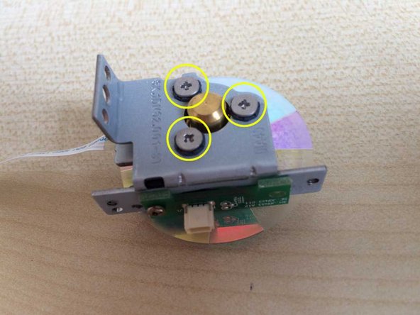
Remove 3 screws and lift them out of their rubber grommets.
-
Holding it by the ribbon cable, rotate the bare colour wheel through 90 degrees in order to remove it.
-
No further disassembly is feasible, and the bearing is not accessible for lubrication. Flicking the edge with a finger, the wheel should spin completely freely.
-


To reassemble your device, follow these instructions in reverse order.
To reassemble your device, follow these instructions in reverse order.

팀
