소개
This guide will help to ajust the sensivity (velocity) of pads on Akai MPD18. Maybe on MPD32, MPD218 and other series it will also work. I didn’t find any simular guides how to do this in internet so I decided to do it by myself. I did it because some of my pads (lower half) after 8 years of use lost it’s velocity and pads became tough to use.
Remember! This is not official modification so I’m not responsible for all possible failures at this work. You’re doing it at your own risk.
필요한 것
-
-
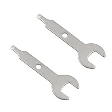
Begin disassembling the device. First, you need to remove the fader by pulling it at yourself using two fingers.
-
-
-
-
Now use your solder iron for changing velocity of the pads.
-
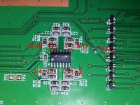
To inscrease velocity of four pads group you need to change the BIAS resistor near the operation amplifier (LMV324M) IC.
-
The higher resistor you will take - more sensivity you will get. The default resistor is 27K so you have to take replacement HIGHER than this value. For my pads it worked at 100K and 56K (because there's a difference on sensivity).
-
The amplification coefficient equals (1 + R2/R1). Default R2 = 27K and R1 = 10K so it equals 3.7. If you're using 100K resistor it equals 11.
-
(If you'll remove this resistor, then sensivity will increase very high so it will react even if you're clap near the sensors, so choose it reasonably).
-
To change sensivity on generic pad you have to solder the little capacitor between reference line and output line of this pad. The capacity must be relativly high. At my pads it worked at 68n-100n. Lower capacity will not work, higher will cause phantom clicking.
-
That all! Now you can assemble it and test.
-


To assemble device do the instructions backward (of course without soldering again.)