소개
Use this guide to remove or replace the display on an Asus ROG G751JL.
필요한 것
-
-
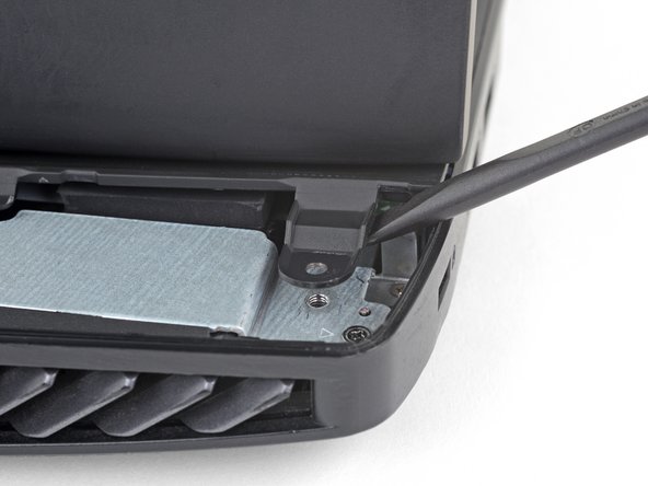
Use an opening tool to pry up the small rubber cover on the upper right corner of the RAM access door.
-
-
-
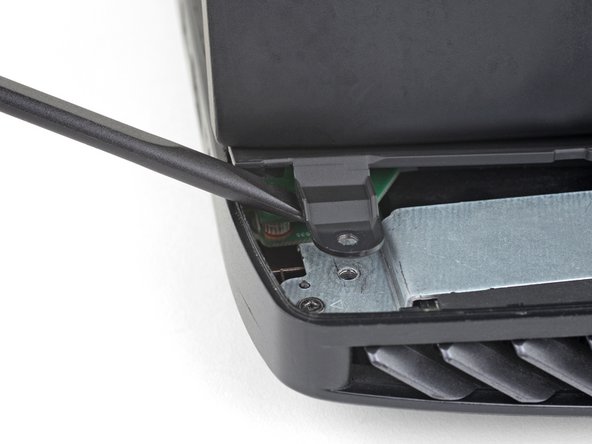
Insert the wide edge of an opening pick into a new part of the seam between the door and the computer.
-
Pry the door up to release the clips closest to the pick.
-
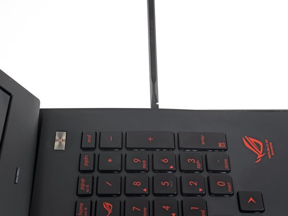
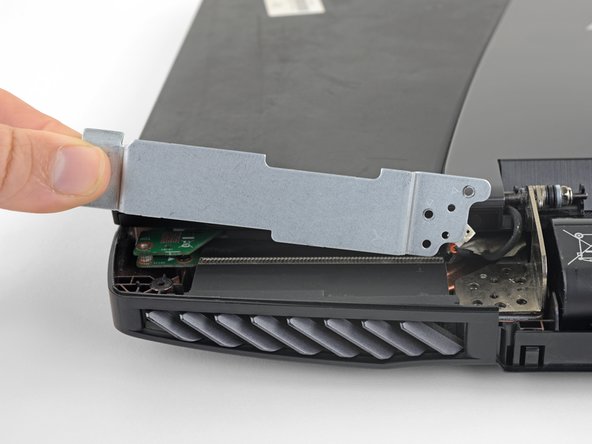
Continue to slide the pick along the seam all the way around the door, prying as you go, until all the clips holding the door down have been released.
-
-
-
Use the point of a spudger to pry out eleven rubber plugs covering the screws on the bottom of the laptop.
-
-
-
-
Flip the laptop right-side up.
-
Use an opening pick to pry the left and right edges of the battery cover away from the laptop enough that you can grip the cover with your fingers.
-
-
-
Pull the speaker connectors straight away from each other to disconnect the speaker cable.
-
-
-
Open the laptop's display to a 90° angle.
-
Use a spudger to pry against one of the screw tabs on the back of the upper case assembly.
-
Repeat this procedure with the other tab.
-
-
-
Use the tip of a spudger to flip up the small locking flap of the keyboard backlight cable ZIF connector.
-
Gently pull the cable out of its socket.
-
-
-
Pull the battery cable away from the connector in the same direction as the individual wires are running to disconnect the battery.
-
-
-
Grab the black tape attached to the display cable and pull straight up to disconnect the display cable.
-


To reassemble your device, follow the above steps in reverse order.
Take your e-waste to an R2 or e-Stewards certified recycler.
Repair didn’t go as planned? Check out our Answers community for troubleshooting help.
To reassemble your device, follow the above steps in reverse order.
Take your e-waste to an R2 or e-Stewards certified recycler.
Repair didn’t go as planned? Check out our Answers community for troubleshooting help.
다른 5명이 해당 안내서를 완성하였습니다.
팀

USF Tampa, Team 2-1, Sullivan Fall 2016 USF Tampa, Team 2-1, Sullivan Fall 2016 회원
USFT-SULLIVAN-F16S2G1
4 회원들
안내서 20개 작성하였습니다
댓글 3개
You have left out TWO very important steps. A) tools needed: a - fine tweezer and b - magnifier glass [ and a lot of patience }.
With the open computer facing you. On the left side two gold electrode wires connect to the motherboard, note the wire placement of the two.
On the right side there is a ribbon connector on the right side. NOTE, when the monitor is lifted out, these will COME OFF. If you are a notice, you will be lost. My guess the new monitor will have these connector. To rebuild: place the set screws for the monitor and then the left and right rear brackets. Go back to front view and insert the back ribbon connector to the motherboard on the right backside. Take a break. Use the magnifier glass and tweezer and attempt to align the SMALL ELECTRODE heads. When aligned they can be pressed on, a light snap will be heard. Please be carefull. This step took me 1 hour. After these steps, continue re-assembly.
Regard,
D C
Would the display connector be the same for the touchscreen model? Or is there an additional cable/different connector?
TUTO remarquable de clarté