소개
Removing the back cover can be useful if you need to replace it if the screen is broken or if there is some other issue with it. The back cover can also be broken down further, allowing replacement of individual parts found on the back cover assembly if you are able to find individual replacement parts. This guide will not cover disassembly of the back cover itself however, and will only show you how to remove the back cover from the camera.
필요한 것
-
-
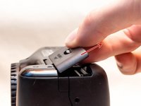
Pry open the rubber I/F terminal cap with your finger.
-
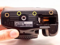
Remove the two M1.7x4.5mm JIS #000 screws that are underneath the I/F terminal cap.
-
Using a plastic pick, or another thin plastic prying tool, pop off the I/F terminal cover from the camera.
-
-
-
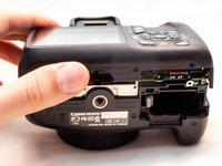
On the left side of the camera, remove the following screw:
-
One M1.7x4.5mm JIS #000 screw
-
On the right side, remove the following screws:
-
One M1.7x5.5mm JIS #000 screw
-
One M1.7x4.5mm JIS #000 screw
-
-
-
-
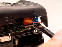
Carefully lift the back cover partially off of the camera.
-
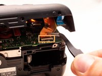
Disconnect the right most ribbon cables from the main PCB board.
-
Use a plastic spudger to lift up the black locking tab.
-
Pull out the ribbon cable from its connector using a pair of angled tweezers.
-
Remove the left ribbon cable using the same two steps as with the other ribbon cable.
-


To reassemble your device, follow these instructions in reverse order.
To reassemble your device, follow these instructions in reverse order.
첨부 문서

팀
