주요 콘텐츠로 건너뛰기

Connecting Cables to the Motherboard

필요한 것

  1. Connecting Cables to the Motherboard, Connecting Cables to the Motherboard: 1 단계, 이미지 1/2 Connecting Cables to the Motherboard, Connecting Cables to the Motherboard: 1 단계, 이미지 2/2
    • Red- Optional ATX Connector

    • Orange- CPU Fan 1

    • Yellow- CPU Fan 2

    • Green- Main ATX Connectors

    • Light Blue- GPU

    • Blue- Panel Connectors

    • Pink- USB Connectors

    • Black- HD Audio

  2. Connecting Cables to the Motherboard, Optional ATX Connector: 2 단계, 이미지 1/2 Connecting Cables to the Motherboard, Optional ATX Connector: 2 단계, 이미지 2/2
    • Connect the two separate six-pin segments to six pins each on the 12-pin PCIE port.

  3. Connecting Cables to the Motherboard, CPU Fan 1: 3 단계, 이미지 1/2 Connecting Cables to the Motherboard, CPU Fan 1: 3 단계, 이미지 2/2
    • Connect the four pin segment to the four pin PCEI connector labeled "CPUFAN1."

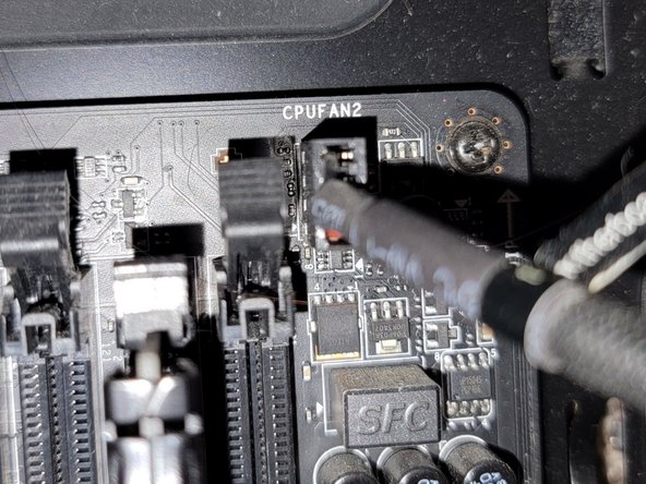
  4. Connecting Cables to the Motherboard, CPU Fan 2: 4 단계, 이미지 1/2 Connecting Cables to the Motherboard, CPU Fan 2: 4 단계, 이미지 2/2
    • Connect the four pin segment to the four pin PCIE port labeled "CPUFAN2."

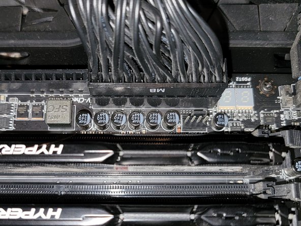
  5. Connecting Cables to the Motherboard, Main ATX Connector: 5 단계, 이미지 1/2 Connecting Cables to the Motherboard, Main ATX Connector: 5 단계, 이미지 2/2
    • Connect the 24 pin segment to the 24 pin PCIE port.

  6. Connecting Cables to the Motherboard, GPU: 6 단계, 이미지 1/2 Connecting Cables to the Motherboard, GPU: 6 단계, 이미지 2/2
    • Connect both of the separate eight pin segments to each of the eight pin PCIE ports on the graphics card.

  7. Connecting Cables to the Motherboard, Panel Connectors (Part 1): 7 단계, 이미지 1/3 Connecting Cables to the Motherboard, Panel Connectors (Part 1): 7 단계, 이미지 2/3 Connecting Cables to the Motherboard, Panel Connectors (Part 1): 7 단계, 이미지 3/3
    • This PCIE port consists of eight pins, two rows of four.

    • Connect the "Power LED+" pin to the pin at the top right corner.

    • Connect the "Power LED-" segment to the pin next to the "Power LED+" segment in the top row.

    • Connect the "Power SW" segment to the two pins on the left side of the top row of pins.

  8. Connecting Cables to the Motherboard, Panel Connectors (Part 2): 8 단계, 이미지 1/3 Connecting Cables to the Motherboard, Panel Connectors (Part 2): 8 단계, 이미지 2/3 Connecting Cables to the Motherboard, Panel Connectors (Part 2): 8 단계, 이미지 3/3
    • Connect the "HDD LED" segment to the two pins on the right side of the bottom row of pins.

    • Connect the "Reset SW" segment to the two pins on the left side of the bottom row of pins.

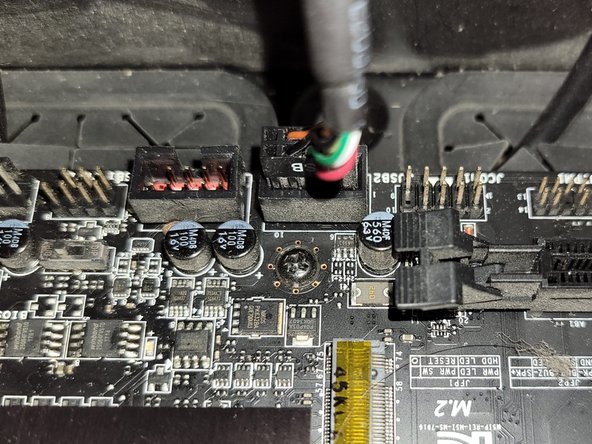
  9. Connecting Cables to the Motherboard, USB Connector: 9 단계, 이미지 1/2 Connecting Cables to the Motherboard, USB Connector: 9 단계, 이미지 2/2
    • Connect the nine pin segment to the nine pin PCIE port.

  10. Connecting Cables to the Motherboard, HD Audio: 10 단계, 이미지 1/2 Connecting Cables to the Motherboard, HD Audio: 10 단계, 이미지 2/2
    • Connect the nine pin segment to the nine pin PCIE port.

결론

To disconnect the cable ties, follow these directions in reverse order.

Grace Parsekian

회원 가입일: 12/05/23

181 평판

안내서 1개 작성함

댓글 0개

댓글 쓰기

조회 통계:

24 시간 전: 10

7일 전: 85

30일 전: 444

전체 시간: 1,439