주요 콘텐츠로 건너뛰기

이 버전에는 잘못된 편집 사항이 있을 수 있습니다. 최신 확인된 스냅샷으로 전환하십시오.

필요한 것

  1. 이 단계는 번역되지 않았습니다. 번역을 도와주십시오

    : 1 단계, 이미지 1/3 : 1 단계, 이미지 2/3 : 1 단계, 이미지 3/3
    • Remove the two 11.6 mm T9 screws from the right side of the back of the printer.

  2. 이 단계는 번역되지 않았습니다. 번역을 도와주십시오

    : 2 단계, 이미지 1/3 : 2 단계, 이미지 2/3 : 2 단계, 이미지 3/3
    • Pull down the front panel to expose the screws on the front.

    • Remove the one 11.6 mm T9 screw on the left side of the front face.

  3. 이 단계는 번역되지 않았습니다. 번역을 도와주십시오

    : 3 단계, 이미지 1/2 : 3 단계, 이미지 2/2
    • Remove the side panel by pushing down and towards the back.

    • This step may be easier if the printer is laid on its side with the left side panel facing up.

  4. 이 단계는 번역되지 않았습니다. 번역을 도와주십시오

    : 4 단계, 이미지 1/3 : 4 단계, 이미지 2/3 : 4 단계, 이미지 3/3
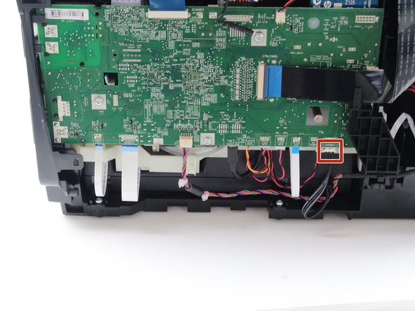
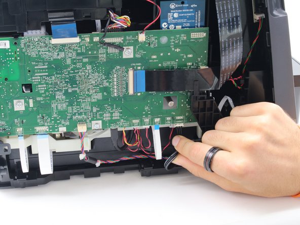
    • Remove the the black cable from the bottom of the motherboard by carefully pulling down on the connection.

  5. 이 단계는 번역되지 않았습니다. 번역을 도와주십시오

    : 5 단계, 이미지 1/2 : 5 단계, 이미지 2/2
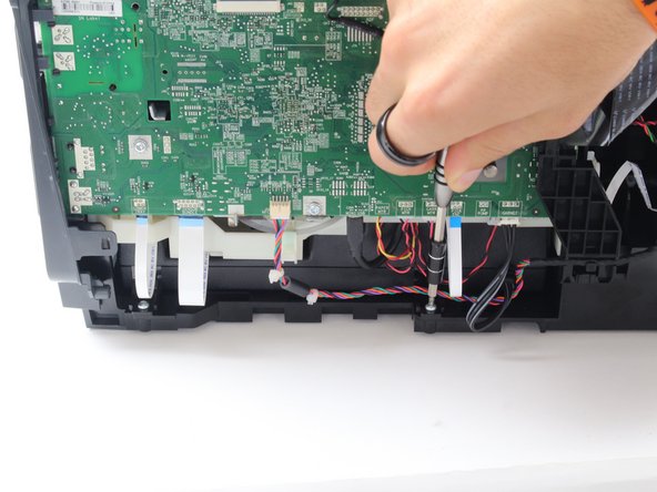
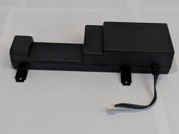
    • Remove the two 9.3 mm T9 screws that attach the power supply to the bottom of the printer.

  6. 이 단계는 번역되지 않았습니다. 번역을 도와주십시오

    : 6 단계, 이미지 1/2 : 6 단계, 이미지 2/2
    • Slide the power supply out of the printer by pulling towards you.

    • Be careful of the wires coming from the motherboard.

결승점

다른 2명이 해당 안내서를 완성하였습니다.

Cole Andrews

회원 가입일: 10/08/18

273 평판

안내서 2개 작성하였습니다

Cal Poly, Team S13-G3, White Fall 2018 Cal Poly, Team S13-G3, White Fall 2018 회원

CPSU-WHITE-F18S13G3

3 회원들

안내서 14개 작성하였습니다

댓글 0개

댓글 쓰기

조회 통계:

24 시간 전: 1

7일 전: 7

30일 전: 14

전체 시간: 454