필요한 것
-
-
Pull the locking tab to the right showing a unlocked symbol.
-
Then pull the release tab to the left, releasing the battery.
-
Lift the battery out of its connection.
-
-
-
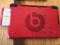
Unscrew the single Phillips #0 screw that holds the optical drive in place.
-
Using a spudger push the optical drive out.
-
Pull the optical drive completely out and set it to the side.
-
-
-
-
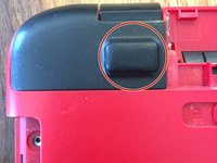
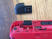
Using a spudger, pry up the rubber cap.
-
Remove the single screw underneath the cap.
-
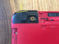
Slightly lift up on the marked section of the hinge cap. Pull away from the computer to release the cap.
-
Remove the hinge screw.
-
Repeat all steps on the other side.
-
-
-
Remove each of the highlighted screws.
-
Note, this screw is sometimes covered by a cap.
-
Remove the silver pan head crew in the optical drive bay.
-
-
-
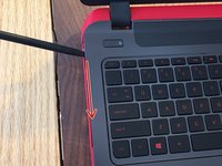
Flip your computer back over and open the display. Using a sputter, opening tool, guitar pick, or card pry up on the top case between the frame and itself.
-
Follow all the way around the top case gently, until the keyboard is able to be lifted freely.
-
NOTE* Do not lift the keyboard off until the next step in which we pull the ribbon cable connections.
-
Using your spudger, or prying tool lift the releases for each ribbon cable. *Be cautious when removing and handling ribbon cables as they are very fragile.
-
Lastly, remove the last two ribbon cables located at the top of the keyboard.
-
-
-
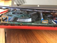
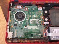
Remove each cable and connection to the logic board.
-
Next, remove the screws holding the motherboard to the bottom case.
-
There may be a screw in this area, there was not in the computer I worked on.
-
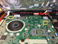
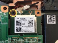
Remove the screw holding the wifi card in place. Pull the wifi card out.
-
-
-
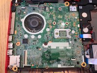
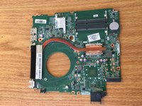
The hardest connection to remove, this is the cable to the AC/DC power port. Remove it by pulling the outside edges of the connector and wiggling gently.
-
-
-
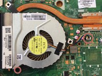
Remove the fan by disconnecting the white pin connector and then removing the only Phillips crew holding the fan in place.
-
Now you're ready to put the new logic board in!
-


To reassemble your device, follow these instructions in reverse order.
To reassemble your device, follow these instructions in reverse order.
다른 9명이 해당 안내서를 완성하였습니다.
팀

댓글 3개
Thanks for this guide. Apparently the RAM is on the underside of the logic board?
I have a HP 15-P189NA which could do with a RAM upgrade.
Das Modell 15-P151NG ist etwas anders, hilft trotzdem die Anleitung.
Ich wäre an dem defekten Mainboard interessiert.