주요 콘텐츠로 건너뛰기

이 버전에는 잘못된 편집 사항이 있을 수 있습니다. 최신 확인된 스냅샷으로 전환하십시오.

필요한 것

  1. 이 단계는 번역되지 않았습니다. 번역을 도와주십시오

    : 1 단계, 이미지 1/3 : 1 단계, 이미지 2/3 : 1 단계, 이미지 3/3
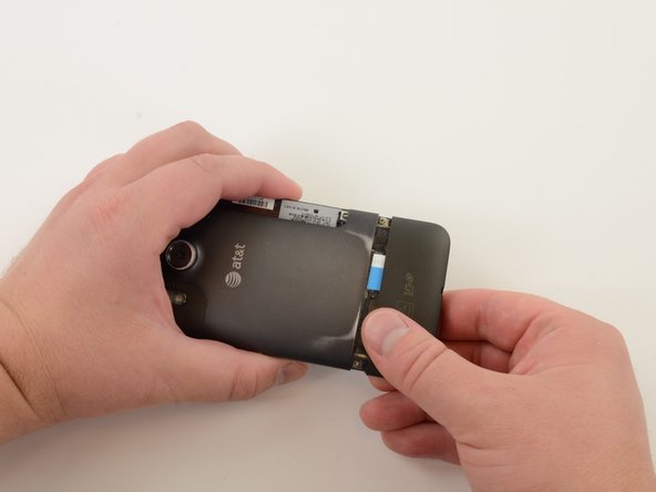
    • Remove battery cover using a plastic opening tool or finger nail.

    • Slide opening tool to release clasps and remove battery cover.

  2. 이 단계는 번역되지 않았습니다. 번역을 도와주십시오

    : 2 단계, 이미지 1/3 : 2 단계, 이미지 2/3 : 2 단계, 이미지 3/3
    • With the cover removed, the battery will fall freely with a gentle shake.

  3. 이 단계는 번역되지 않았습니다. 번역을 도와주십시오

    : 3 단계, 이미지 1/2 : 3 단계, 이미지 2/2
    • Remove SIM card cover by simultaneously squeezing cover and pulling it off of the phone.

  4. 이 단계는 번역되지 않았습니다. 번역을 도와주십시오

    : 4 단계, 이미지 1/2 : 4 단계, 이미지 2/2
    • Slide SIM card out.

  5. 이 단계는 번역되지 않았습니다. 번역을 도와주십시오

    : 5 단계, 이미지 1/3 : 5 단계, 이미지 2/3 : 5 단계, 이미지 3/3
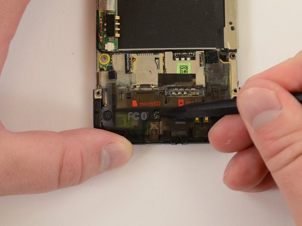
    • Remove Micro SD card by pushing it in to the phone. Spring-loaded clasp will release the card.

  6. 이 단계는 번역되지 않았습니다. 번역을 도와주십시오

    : 6 단계, 이미지 1/2 : 6 단계, 이미지 2/2
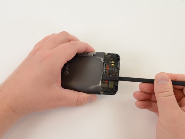
    • Use a curved metal spudger to remove GPS cover.

    • Probe underside of GPS cover until you can force a small opening between GPS cover and back cover of phone.

  7. 이 단계는 번역되지 않았습니다. 번역을 도와주십시오

    : 7 단계, 이미지 1/3 : 7 단계, 이미지 2/3 : 7 단계, 이미지 3/3
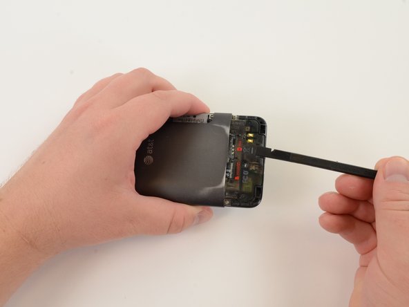
    • Insert plastic opening tool into gap between GPS cover and back cover of phone. Slide tool along GPS cover and pry the piece off.

  8. 이 단계는 번역되지 않았습니다. 번역을 도와주십시오

    : 8 단계, 이미지 1/3 : 8 단계, 이미지 2/3 : 8 단계, 이미지 3/3
    • Remove "VOID" sticker from screw.

    • If your phone has a warranty, removing "VOID" sticker will void your warranty.

  9. 이 단계는 번역되지 않았습니다. 번역을 도와주십시오

    : 9 단계, 이미지 1/2 : 9 단계, 이미지 2/2
    • Remove four 2.2mm T5 torx screws.

    • Remove one 4.5mm T5 torx screw.

  10. 이 단계는 번역되지 않았습니다. 번역을 도와주십시오

    : 10 단계, 이미지 1/2 : 10 단계, 이미지 2/2
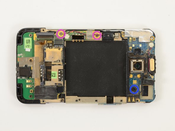
    • Remove display cable shield.

    • Insert probing tool into screw hole and pull shield.

    • Be careful! This piece is made of thin, springy metal and will fly across the room if you remove it too forcefully.

  11. 이 단계는 번역되지 않았습니다. 번역을 도와주십시오

    : 11 단계, 이미지 1/2 : 11 단계, 이미지 2/2
    • Peel off manufacturer's information sticker.

  12. 이 단계는 번역되지 않았습니다. 번역을 도와주십시오

    : 12 단계, 이미지 1/2 : 12 단계, 이미지 2/2
    • Lift volume button assembly out of the back case.

    • Work slowly! Initially, you must lever the assembly from the ribbon cable attaching it to the upper logic board. The cable is delicate.

  13. 이 단계는 번역되지 않았습니다. 번역을 도와주십시오

    : 13 단계, 이미지 1/3 : 13 단계, 이미지 2/3 : 13 단계, 이미지 3/3
    • Push up on the back cover, wiggling cover back and forth, until it slides off.

  14. 이 단계는 번역되지 않았습니다. 번역을 도와주십시오

    : 14 단계, 이미지 1/3 : 14 단계, 이미지 2/3 : 14 단계, 이미지 3/3
    • Remove "VOID" sticker.

    • If your phone has a warranty, removing the "VOID" sticker will void your warranty.

    • Remove three 2.4mm T5 torx screws.

  15. 이 단계는 번역되지 않았습니다. 번역을 도와주십시오

    : 15 단계, 이미지 1/2 : 15 단계, 이미지 2/2
    • Apply pressure to the bottom of the plastic logic board shield and it will pop right off.

  16. 이 단계는 번역되지 않았습니다. 번역을 도와주십시오

    : 16 단계, 이미지 1/2 : 16 단계, 이미지 2/2
    • Remove rubber spacer.

  17. 이 단계는 번역되지 않았습니다. 번역을 도와주십시오

    : 17 단계, 이미지 1/2 : 17 단계, 이미지 2/2
    • Peel off Mylar tape.

  18. 이 단계는 번역되지 않았습니다. 번역을 도와주십시오

    : 18 단계, 이미지 1/2 : 18 단계, 이미지 2/2
    • Peel off electrical tape.

  19. 이 단계는 번역되지 않았습니다. 번역을 도와주십시오

    : 19 단계, 이미지 1/3 : 19 단계, 이미지 2/3 : 19 단계, 이미지 3/3
    • Pry display assembly connector off of lower logic board.

  20. 이 단계는 번역되지 않았습니다. 번역을 도와주십시오

    : 20 단계, 이미지 1/2 : 20 단계, 이미지 2/2
    • Remove metal bracket.

  21. 이 단계는 번역되지 않았습니다. 번역을 도와주십시오

    : 21 단계, 이미지 1/3 : 21 단계, 이미지 2/3 : 21 단계, 이미지 3/3
    • Remove speaker.

    • During reassembly, be careful with the spring connectors on the reverse side of the speaker unit. They are bent easily.

    • This rubber spacer is held on by a weak adhesive. Be careful with this during reassembly, as it may catch and crumple as you put the back panel back the phone.

  22. 이 단계는 번역되지 않았습니다. 번역을 도와주십시오

    : 22 단계, 이미지 1/1
    • Remove one 1.5mm #00 Phillips screw.

    • Remove two 2.5mm T5 torx screws.

  23. 이 단계는 번역되지 않았습니다. 번역을 도와주십시오

    : 23 단계, 이미지 1/2 : 23 단계, 이미지 2/2
    • Remove earpiece speaker connector.

  24. 이 단계는 번역되지 않았습니다. 번역을 도와주십시오

    : 24 단계, 이미지 1/3 : 24 단계, 이미지 2/3 : 24 단계, 이미지 3/3
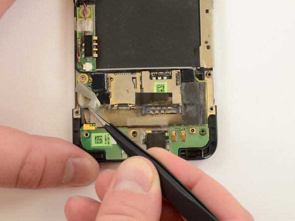
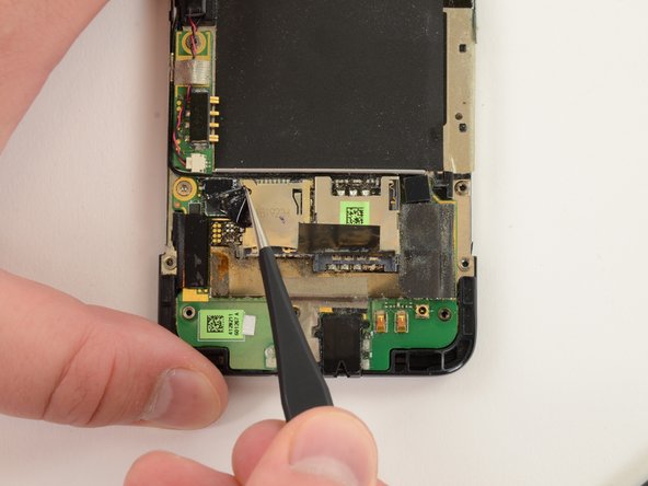
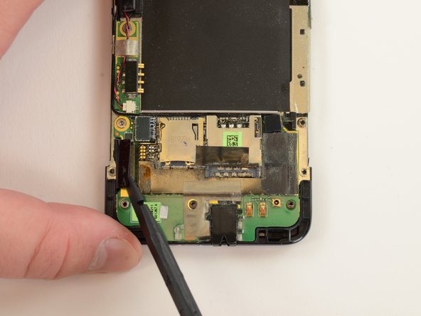
    • Pry off Bluetooth coaxial cable connector.

    • Unwind Bluetooth coaxial cable from plastic camera shield.

  25. 이 단계는 번역되지 않았습니다. 번역을 도와주십시오

    : 25 단계, 이미지 1/3 : 25 단계, 이미지 2/3 : 25 단계, 이미지 3/3
    • Pry off plastic camera shield.

  26. 이 단계는 번역되지 않았습니다. 번역을 도와주십시오

    : 26 단계, 이미지 1/2 : 26 단계, 이미지 2/2
    • Heat black Mylar shield for easier removal.

    • As you can see, we attempted to peel off the Mylar shield before heating it. It required more force than we were comfortable with, so we turned up the heat!

    • Peel off Mylar shield.

  27. 이 단계는 번역되지 않았습니다. 번역을 도와주십시오

    : 27 단계, 이미지 1/2 : 27 단계, 이미지 2/2
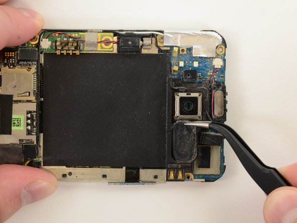
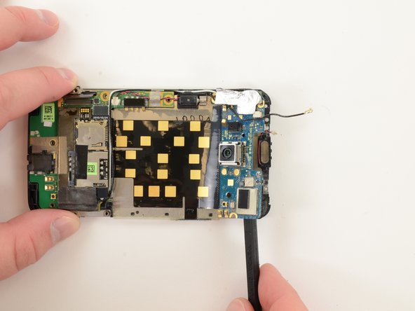
    • Gently separate upper logic board from mid chassis. The upper logic board is held to the mid chassis by copious amounts of strong adhesive.

  28. 이 단계는 번역되지 않았습니다. 번역을 도와주십시오

    : 28 단계, 이미지 1/2 : 28 단계, 이미지 2/2
    • Gently separate lower logic board from mid chassis. The lower logic board is held to the mid chassis by copious amounts of strong adhesive.

  29. 이 단계는 번역되지 않았습니다. 번역을 도와주십시오

    : 29 단계, 이미지 1/1
    • Once the adhesive-laden logic boards are separated from the mid chassis, the entire assembly easily comes off.

    • Be careful when handing the logic board assembly. We could have separated out each part, but decided it was a waste of time. The cost of cutting this corner is extra care when handling the logic board assembly.

  30. 이 단계는 번역되지 않았습니다. 번역을 도와주십시오

    : 30 단계, 이미지 1/2 : 30 단계, 이미지 2/2
    • Blast the front panel with heat and pry between the display assembly and front panel bezel, working one or several guitar picks around the display assembly.

    • Once the display assembly is loosened from the front panel, it will fall away.

    • The front glass came off easily, but the digitizer was much more difficult to remove. The adhesive holding together the display assembly is much weaker than the adhesive holding the display assembly to the front panel.

    • While creating this guide, I utterly destroyed the front panel bezel and digitizer. Replacing the display assembly was a breeze--but removing the digitizer required nearly a dozen reheats of the front panel. To replace the bezel, you will need a new "mid chassis" (that's the front panel piece the digitizer is so powerfully glued to).

결승점

다른 17명이 해당 안내서를 완성하였습니다.

Jeff Snyder

회원 가입일: 02/07/13

8,802 평판

안내서 4개 작성하였습니다

iFixit iFixit 회원

Staff

135 회원들

안내서 16,817개 작성하였습니다

댓글 0개

댓글 쓰기

조회 통계:

24 시간 전: 0

7일 전: 2

30일 전: 3

전체 시간: 5,347