주요 콘텐츠로 건너뛰기

Hover-1 Chrome Left Gyroscope Sensor Board Replacement

필요한 것

  1. Hover-1 Chrome Left Gyroscope Sensor Board Replacement, Hover-1 Chrome Disassembly: 1 단계, 이미지 1/1
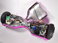
    • Flip the Hover-1 Chrome upside down.

    • Use a Phillips #2 screwdriver to remove the fourteen 14 mm screws from the bottom of the Hover-1.

    • Break the two black tape circles, and remove the two 15 mm Phillips screws underneath.

  2. Hover-1 Chrome Left Gyroscope Sensor Board Replacement: 2 단계, 이미지 1/1
    • Lift the shell without the speaker grille and unplug the battery.

  3. Hover-1 Chrome Left Gyroscope Sensor Board Replacement: 3 단계, 이미지 1/2 Hover-1 Chrome Left Gyroscope Sensor Board Replacement: 3 단계, 이미지 2/2
    • Lift the shell with the speaker grille.

    • Unplug the speaker.

    • Unplug the LEDs.

    • Unplug the power button

    • Unplug the charging port.

  4. Hover-1 Chrome Left Gyroscope Sensor Board Replacement, Left Gyroscope Sensor Board: 4 단계, 이미지 1/3 Hover-1 Chrome Left Gyroscope Sensor Board Replacement, Left Gyroscope Sensor Board: 4 단계, 이미지 2/3 Hover-1 Chrome Left Gyroscope Sensor Board Replacement, Left Gyroscope Sensor Board: 4 단계, 이미지 3/3
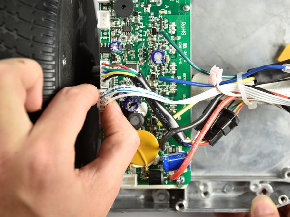
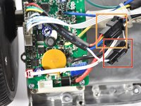
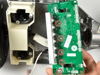
    • Disconnect the speaker cable.

    • Disconnect the cable that travels to the other sensor board.

  5. Hover-1 Chrome Left Gyroscope Sensor Board Replacement: 5 단계, 이미지 1/3 Hover-1 Chrome Left Gyroscope Sensor Board Replacement: 5 단계, 이미지 2/3 Hover-1 Chrome Left Gyroscope Sensor Board Replacement: 5 단계, 이미지 3/3
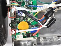
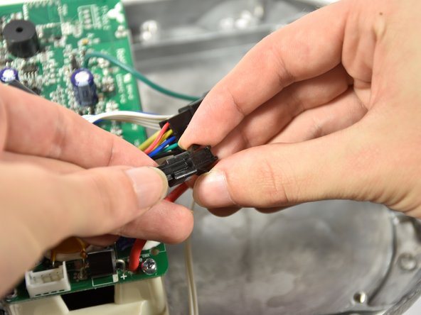
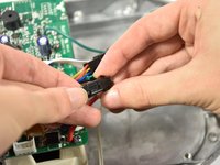
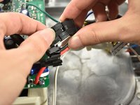
    • Disconnect the smaller connector midway on the cable.

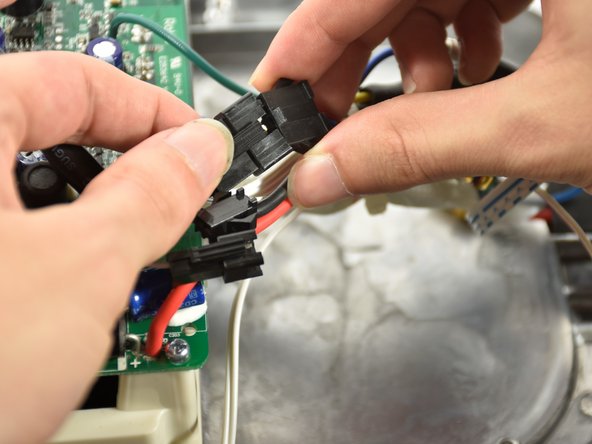
    • Disconnect the larger connector midway on the cable.

  6. Hover-1 Chrome Left Gyroscope Sensor Board Replacement: 6 단계, 이미지 1/1
    • Remove the four 12mm Phillips #2 screws securing the sensor board.

  7. Hover-1 Chrome Left Gyroscope Sensor Board Replacement: 7 단계, 이미지 1/2 Hover-1 Chrome Left Gyroscope Sensor Board Replacement: 7 단계, 이미지 2/2
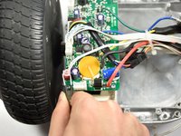
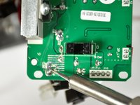
    • Locate the five solder locations on the underside of the gyroscope sensor board.

    • Plug in soldering iron and wait for the tip tip to reach its target temperature.

    • Rest the tip of the iron on the solder and wait for the solder to melt. The wire will drop out of the sensor board.

    • Be aware of where the tip of the soldering iron is at ALL times. Put on safety glasses before picking up the soldering iron. Turn on a fan and face it towards the device to vent harmful fumes away from the solderers face.

결론

To reassemble your device, follow these instructions in reverse order.

Nick McGuire

회원 가입일: 10/08/18

551 평판

안내서 4개 작성하였습니다

Cal Poly, Team S4-G1, White Fall 2018 Cal Poly, Team S4-G1, White Fall 2018 회원

CPSU-WHITE-F18S4G1

4 회원들

안내서 6개 작성하였습니다

댓글 0개

댓글 쓰기

조회 통계:

24 시간 전: 1

7일 전: 4

30일 전: 8

전체 시간: 1,086