이 버전에는 잘못된 편집 사항이 있을 수 있습니다. 최신 확인된 스냅샷으로 전환하십시오.
필요한 것
-
이 단계는 번역되지 않았습니다. 번역을 도와주십시오
-
A continuity test tells us whether two things are electrically connected: if something is continuous, an electric current can flow freely from one end to the other.
-
If there's no continuity, it means there is a break somewhere in the circuit. This could indicate anything from a blown fuse or bad solder joint to an incorrectly wired circuit.
-
-
이 단계는 번역되지 않았습니다. 번역을 도와주십시오
-
Plug the black probe into the COM port on your multimeter.
-
Plug the red probe into the port labeled with a V symbol (in this case, the right port).
-
-
이 단계는 번역되지 않았습니다. 번역을 도와주십시오
-
Switch on your multimeter, and set the dial to continuity mode (indicated by an icon that looks like a sound wave).
-
-
이 단계는 번역되지 않았습니다. 번역을 도와주십시오
-
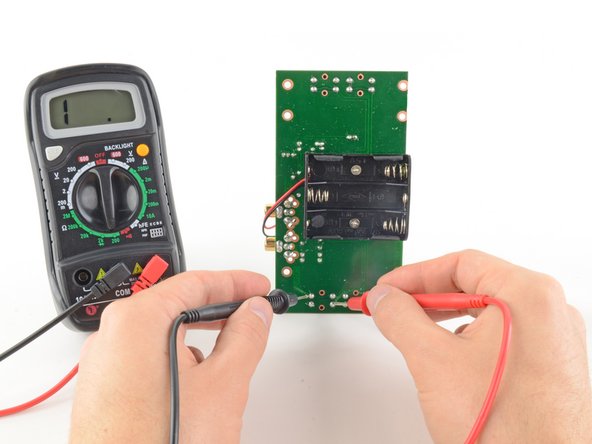
To complete your continuity test, place one probe at each end of the circuit or component you want to test.
-
To check for this, reverse what the probes are touching and check for continuity. If the multimeter shows continuity, then it's possibly a diode.
-
-
-
이 단계는 번역되지 않았습니다. 번역을 도와주십시오
-
Turn the dial to the resistance mode.
-
If your multimeter has manual ranging, set the resistance to the lowest setting.
-
-
이 단계는 번역되지 않았습니다. 번역을 도와주십시오
-
In this mode, the multimeter sends a little current through one probe, and measures what (if anything) is received by the other probe.
-
If the probes are connected—either by a continuous circuit, or by touching each other directly—the test current flows through. The screen displays a value of zero (or near zero—in this case, 0.8). Very low resistance is another way of saying that we have continuity.
-
If no current is detected, it means there's no continuity. The screen will display 1 or OL (open loop).
-
-
이 단계는 번역되지 않았습니다. 번역을 도와주십시오
-
To complete your continuity test, place one probe at each end of the circuit or component you want to test.
-
As before, if your circuit is continuous, the screen displays a value of zero (or near zero).
-
If the screen displays 1 or OL (open loop), there's no continuity—that is, there's no path for electric current to flow from one probe to the other.
-
-
이 단계는 번역되지 않았습니다. 번역을 도와주십시오
-
Plug the black probe into the COM port on your multimeter.
-
Plug the red probe into the port labeled with a V symbol (in this case, the right port).
-
-
이 단계는 번역되지 않았습니다. 번역을 도와주십시오
-
Switch on your multimeter, and set the dial to DC voltage mode (indicated by a V with a straight line, or the symbol ⎓).
-
Each setting on the dial lists the maximum voltage it can measure. So for example, if you expect to measure more than 2 volts but less than 20, use the 20 volt setting.
-
If you're not sure, start with the highest setting.
-
-
이 단계는 번역되지 않았습니다. 번역을 도와주십시오
-
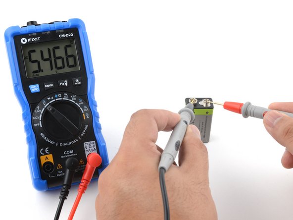
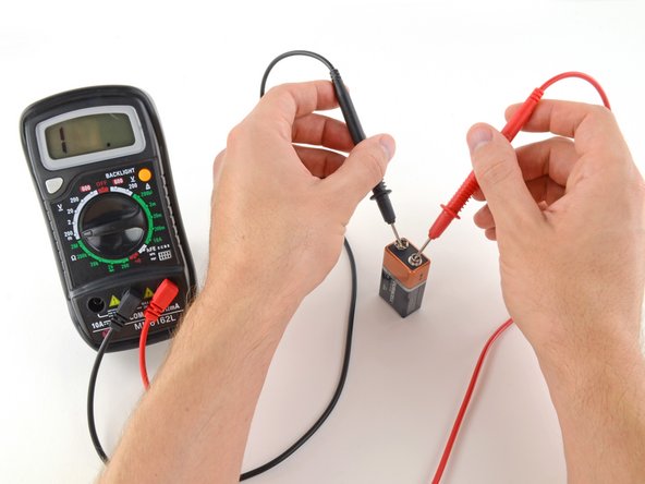
Place the red probe on the positive terminal, and the black probe on the negative terminal. The multimeter will display the measured voltage.
-
Skip the next step, which describes how to measure voltage using manual ranging multimeters.
-
-
이 단계는 번역되지 않았습니다. 번역을 도와주십시오
-
Place the red probe on the positive terminal, and the black probe on the negative terminal.
-
If your range was set too high, you may not get a very precise reading. Here the multimeter reads 9 volts. That's fine, but we can turn the dial to a lower range to get a more precise.
-
If you set the range too low, the multimeter simply reads 1 or OL, indicating that it is overloaded or out of range. This won't hurt the multimeter, but we need to set the dial to a higher range.
-
-
이 단계는 번역되지 않았습니다. 번역을 도와주십시오
-
To begin, make sure no current is running through the circuit or component you want to measure. Switch it off, unplug it from the wall, and remove any batteries.
-
Plug the black probe into the COM port on your multimeter.
-
Plug the red probe into the port labeled with an Ω symbol (in this case, the right port).
-
-
이 단계는 번역되지 않았습니다. 번역을 도와주십시오
-
Place one probe at each end of the circuit or component you want to measure.
-
If your multimeter is manual ranging:
-
If your multimeter reads close to zero, the range is set too high for a good measurement. Turn the dial to a lower resistance range.
-
If you set the range too low, the multimeter simply reads 1 or OL, indicating that it is overloaded or out of range. This won't hurt the multimeter, but we need to set the dial to a higher range.
-


다른 1004명이 해당 안내서를 완성하였습니다.


댓글 132개
EASy and helpful indeed
Iwant to know hw to test caperstas