주요 콘텐츠로 건너뛰기

Insignia NS-CLLT01 Motherboard Removal

필요한 것

  1. Insignia NS-CLLT01 Motherboard Removal, Motherboard: 1 단계, 이미지 1/2 Insignia NS-CLLT01 Motherboard Removal, Motherboard: 1 단계, 이미지 2/2
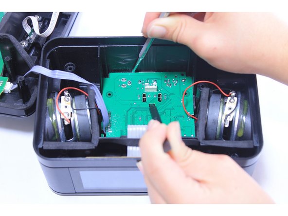
    • Grip the white ribbon cable connector that attaches the lightning cable to the middle of the central circuit board located in the bottom of the clock. Pinch and pull straight up to detach the cable.

  2. Insignia NS-CLLT01 Motherboard Removal: 2 단계, 이미지 1/2 Insignia NS-CLLT01 Motherboard Removal: 2 단계, 이미지 2/2
    • Remove the white ribbon connector that connects the central circuit board to the circuit board attached to the top of the clock by gripping it on both sides and pulling it straight away from the board.

  3. Insignia NS-CLLT01 Motherboard Removal: 3 단계, 이미지 1/1
    • Unscrew the two 10mm screws from the bottom circuit board.

  4. Insignia NS-CLLT01 Motherboard Removal: 4 단계, 이미지 1/3 Insignia NS-CLLT01 Motherboard Removal: 4 단계, 이미지 2/3 Insignia NS-CLLT01 Motherboard Removal: 4 단계, 이미지 3/3
    • Use the narrow end of a plastic spudger to pull back the clip in the center of the board.

    • At the same time, pry the circuit board up by wedging another spudger into the top left-hand corner of the board and working it along the back, pushing the edge of the board away from the back of the clock.

    • The black radio antenna, which is attached to the board and comes out of the back of the clock, will need to be pushed into the clock from the outside as the board is lifted up.

  5. Insignia NS-CLLT01 Motherboard Removal: 5 단계, 이미지 1/1
    • Once the ports on the back of the circuit board are displaced and resting against the back of the clock, use a pair of tweezers to lift the circuit board up off of the bottom of the clock, continuing to feed the radio antenna through the side of the clock as the board lifts up.

  6. Insignia NS-CLLT01 Motherboard Removal: 6 단계, 이미지 1/1
    • Pull the radio antenna the rest of the way through the side of the clock.

  7. Insignia NS-CLLT01 Motherboard Removal: 7 단계, 이미지 1/1
    • Turn the circuit board over.

    • Disconnect the two white connectors on the bottom of the circuit board by gripping the sides of each connector and pulling straight out.

결승점

Preston Jackson

회원 가입일: 09/23/15

201 평판

안내서 2개 작성하였습니다

Baylor, Team 6-9, Williams Fall 2015 Baylor, Team 6-9, Williams Fall 2015 회원

BU-WILLIAMS-F15S6G9

3 회원들

안내서 6개 작성하였습니다

댓글 0개

댓글 쓰기

조회 통계:

24 시간 전: 1

7일 전: 5

30일 전: 7

전체 시간: 225