주요 콘텐츠로 건너뛰기

이 버전에는 잘못된 편집 사항이 있을 수 있습니다. 최신 확인된 스냅샷으로 전환하십시오.

필요한 것

  1. 이 단계는 번역되지 않았습니다. 번역을 도와주십시오

    : 1 단계, 이미지 1/1
    • Using your fingernail, open the battery cover.

  2. 이 단계는 번역되지 않았습니다. 번역을 도와주십시오

    : 2 단계, 이미지 1/1
    • Slide the orange latch sideways to eject the battery.

    • Remove the battery from the battery slot.

  3. 이 단계는 번역되지 않았습니다. 번역을 도와주십시오

    : 3 단계, 이미지 1/3 : 3 단계, 이미지 2/3 : 3 단계, 이미지 3/3
    • Using a Phillips #00 screwdriver, remove two 5.39 mm screws next to the battery slot.

    • Remove the metal piece holding down the lanyard, then remove the lanyard.

  4. 이 단계는 번역되지 않았습니다. 번역을 도와주십시오

    : 4 단계, 이미지 1/3 : 4 단계, 이미지 2/3 : 4 단계, 이미지 3/3
    • Using a Phillips #00 screwdriver, remove seven screws located on the outside case of the camera.

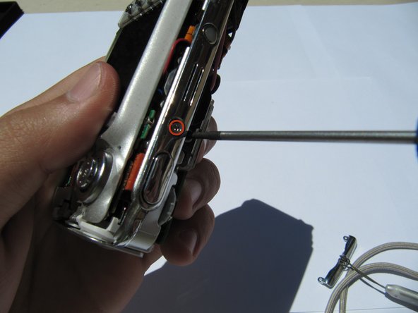
    • One 6.25 mm screw is located on the top right corner, right to the "OK" button.

    • Four 4.45 mm screws are on the bottom of the camera.

    • Two 2.95 mm screws are on the left side of the camera, above the USB port.

  5. 이 단계는 번역되지 않았습니다. 번역을 도와주십시오

    : 5 단계, 이미지 1/2 : 5 단계, 이미지 2/2
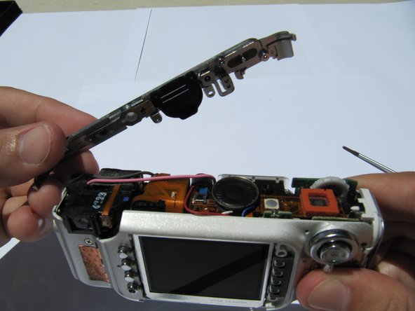
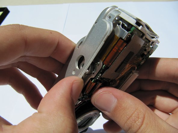
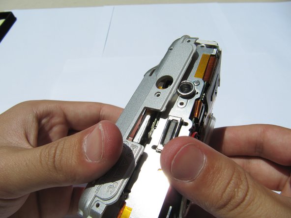
    • Carefully remove the rear camera casing.

    • Carefully remove the front camera casing.

  6. 이 단계는 번역되지 않았습니다. 번역을 도와주십시오

    : 6 단계, 이미지 1/2 : 6 단계, 이미지 2/2
    • Remove the top panel screw (1x 4.37mm).

  7. 이 단계는 번역되지 않았습니다. 번역을 도와주십시오

    : 7 단계, 이미지 1/2 : 7 단계, 이미지 2/2
    • Remove the top panel.

  8. 이 단계는 번역되지 않았습니다. 번역을 도와주십시오

    : 8 단계, 이미지 1/2 : 8 단계, 이미지 2/2
    • Remove the back panel screws (1x 3.33mm, and 1x 3.40mm).

  9. 이 단계는 번역되지 않았습니다. 번역을 도와주십시오

    : 9 단계, 이미지 1/3 : 9 단계, 이미지 2/3 : 9 단계, 이미지 3/3
    • Separate the inner casing from the tripod mount.

  10. 이 단계는 번역되지 않았습니다. 번역을 도와주십시오

    : 10 단계, 이미지 1/3 : 10 단계, 이미지 2/3 : 10 단계, 이미지 3/3
    • Gently pull the orange tab out of the circuit board.

  11. 이 단계는 번역되지 않았습니다. 번역을 도와주십시오

    : 11 단계, 이미지 1/2 : 11 단계, 이미지 2/2
    • Carefully separate and flip over the LCD panel to expose the central circuit board.

  12. 이 단계는 번역되지 않았습니다. 번역을 도와주십시오

    : 12 단계, 이미지 1/1
    • Remove the (1x 3.33mm) screw from the menu button panel .

  13. 이 단계는 번역되지 않았습니다. 번역을 도와주십시오

    : 13 단계, 이미지 1/2 : 13 단계, 이미지 2/2
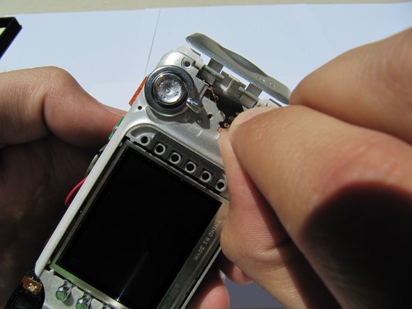
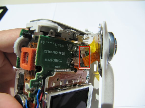
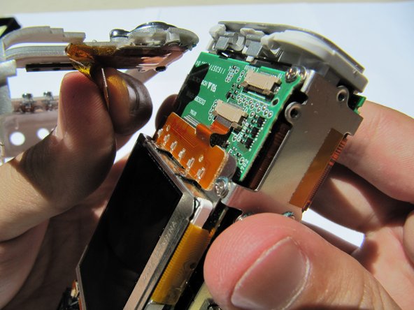
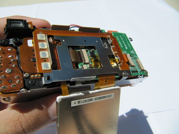
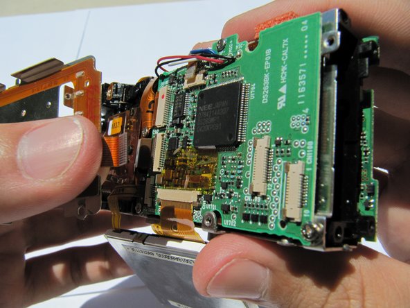
    • Pull the second orange tab from the circuit board and remove the buttons.

결승점

다른 한 분이 해당 안내서를 완성하였습니다.

Michael

회원 가입일: 06/24/10

63 평판

안내서 2개 작성하였습니다

Cal Poly, Team 2-8, Johann Summer 2010 Cal Poly, Team 2-8, Johann Summer 2010 회원

CPSU-JOHANN-R10S2G8

5 회원들

안내서 16개 작성하였습니다

댓글 0개

댓글 쓰기

조회 통계:

24 시간 전: 0

7일 전: 6

30일 전: 7

전체 시간: 1,357