소개
IO 보드는 Mac Pro의 모든 포트를 호스팅합니다: Thunderbolt, USB, 3.5mm 스피커 및 헤드폰 잭, 이더넷 포트 및 HDMI. 이 안내서를 사용하여 IO 보드를 교체하십시오.
Mac Pro에서 어떠한 작업이든 시작하기 전에: 전원 선을 뽑고, 전원 버튼을 10초 이상 눌러서 전원 공급 장치의 캐패시터를 방전시켜 주세요.
전원 공급 장치 뒷면에 노출된 납땜 연결부나 캐퍼시터 부분을 만지지 않도록 매우 조심하세요. 기판의 가장자리 만을 잡아서 옮겨주세요.
필요한 것
-
-
팬 어셈블리의 바깥 둘레에 있는 5.1mm T10 Torx 나사 다섯 개를 풀어주세요.
Fat Mango is correct. That said. If you do pull the fan assembly note that the screws are all held in with blue Permatex and breaking them free takes a fair amount of effort. Getting a good set of Torx screwdrivers is a must.
Jim WIlson - 답글
Hey guys, what would happen if you only replace one card.. I have a D300 but the plan is to upgrade to D500 or D600. So If I can afford and install one instead of the pair would it increase something? or will it cause any conflict? I guess I don’t understand if I the Mac Pro has 2 D300 graphic cards that means each has 1GB? Same as If I would Install 1 D600 that would increase 3GB only? Thanks.
D300 = 2GB each card. Very few apps uses two cards at the same time.
Gio Cas -
The (5) Screws are Apple part number 923-0713
-
-
-
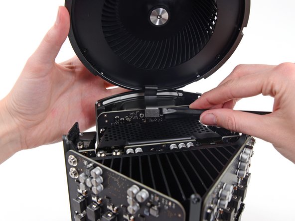
한 손으로 팬 어셈블리를 받치면서 팬 케이블 브래킷에서 T8 고정 나사 두 개를 풀어주세요.
On my machine, a TR7 worked to remove them due to the weird angle.
-
-
-
-
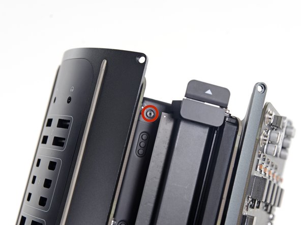
상호 연결 보드를 방열판에 고정하는 6.0mm T8 Torx 나사 두 개를 풀어주세요.
Ended up being T9 screws for me.
T8 screws for me, i did and edit to this step
Ended up being T15 screws on my machine
-
-
-
스퍼저의 평평한 끝으로 IO 보드의 소켓에서 전원 공급 장치의 DC 출력 커넥터를 연결 해제하세요.
-
스퍼저의 뾰족한 끝으로 IO 보드의 소켓에서 전원 공급 장치 데이터 케이블을 연결 해제하세요.
Need to add T9 Torx Screwdriver to list of tools at the beginning of this article.
-
-
-
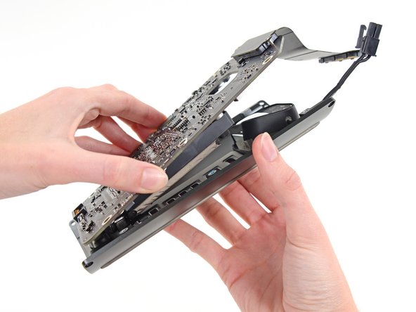
전원 공급 장치 측면에서 9.0mm 은색 T10 Torx 나사 네 개를 풀어주세요.
-
-
-
IO 보드를 IO 쉴드에 고정하는 9mm T10 Torx 나사 두 개를 풀어주세요.
On reassembly, before tightening these 2 9.0mm T10s, make sure the other 4 holes line up. Otherwise you might be setting yourself up for cross threading the 4 remaining 9.0 mm T10 that are already in a bad spot for torquing.
Might not be a bad idea to put the other 4 halfway in to be sure no resistance, then tighten the 2 in this step, then remove the other 4.
-
-
-
스퍼저의 뾰족한 끝으로 IO 실드 리본 케이블 ZIF 커넥터의 고정 플랩을 젖혀주세요.
-
IO 실드 리본 케이블을 연결 해제하세요.
-
-
-
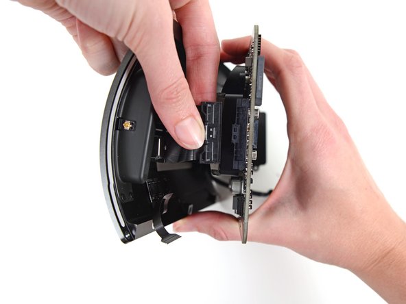
IO 보드에서 오디오 잭 리본 케이블 커넥터를 꽉 쥐고 당겨 빼내세요.
-


기기를 재조립하려면, 이 지침을 역순으로 수행해 주세요.
기기를 재조립하려면, 이 지침을 역순으로 수행해 주세요.
다른 5명이 해당 안내서를 완성하였습니다.
다음 번역가들에게 특별히 감사 드립니다:
100%


이 번역자 분들은 저희가 세상을 수리하는데 동참해 주시는 분입니다! 기여하시겠습니까?
번역 시작하기 ›

댓글 3개
How do you even get the a t10 to fit a such an aggressive angle?
My USB ports don’t work.. I replaced this board and they still don’t work.. Suggestions as to what could be causing this?
I’m having a severe problem with the data cable the runs from the power supply to the IO board. First, I broke a couple of the pins, so I had to order a new IO board. Now the pins are slightly different. Before, they were just sitting out unprotected, but the new board I purchased has a type of barrier around it, but my data cable won’t fit onto the pins now with the new protective barriers. Please help!