이 버전에는 잘못된 편집 사항이 있을 수 있습니다. 최신 확인된 스냅샷으로 전환하십시오.
필요한 것
-
이 단계는 번역되지 않았습니다. 번역을 도와주십시오
-
Remove the following ten screws:
-
Two 8 mm 5-point Pentalobe screws
-
Eight 2.5 mm 5-point Pentalobe screws
-
-
이 단계는 번역되지 않았습니다. 번역을 도와주십시오
-
Wedge your fingers between the display and the lower case and pull upward to pop the lower case off the Air.
-
-
이 단계는 번역되지 않았습니다. 번역을 도와주십시오
-
Use the flat end of a spudger to pry both short sides of the battery connector upward to disconnect it from its socket on the logic board.
-
Bend the battery cable slightly away from the logic board so the connector will not accidentally bend back and make contact with its socket.
-
-
이 단계는 번역되지 않았습니다. 번역을 도와주십시오
-
Use the flat end of a spudger to pry the left and right I/O board cable connectors up off their respective sockets on the I/O board.
-
-
이 단계는 번역되지 않았습니다. 번역을 도와주십시오
-
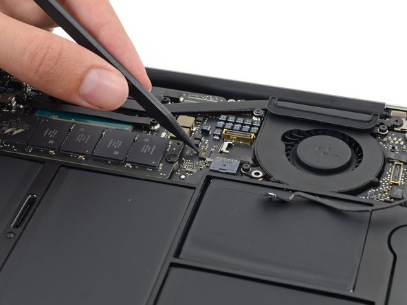
Use the tip of a spudger to carefully push on each side of the iSight camera cable connector to loosen it out of its socket on the logic board.
-
-
이 단계는 번역되지 않았습니다. 번역을 도와주십시오
-
Peel the iSight camera cable up off the adhesive securing it to the fan.
-
-
-
이 단계는 번역되지 않았습니다. 번역을 도와주십시오
-
Use the tip of a spudger to carefully flip up the retaining flap on the fan cable ZIF socket.
-
-
이 단계는 번역되지 않았습니다. 번역을 도와주십시오
-
Remove the following three screws securing the fan to the upper case:
-
Two 5.5 mm T5 Torx screws
-
One 4.6 mm T5 Torx screw
-
-
이 단계는 번역되지 않았습니다. 번역을 도와주십시오
-
Lift, but do not remove the fan out of its recess in the upper case.
-
Carefully pull the fan ribbon cable out of its socket as you remove the fan from the Air.
-
-
이 단계는 번역되지 않았습니다. 번역을 도와주십시오
-
Remove the following five screws securing the battery to the upper case:
-
Two 5.2 mm T5 Torx screws
-
One 6 mm T5 Torx screw
-
Two 2.6 mm T5 Torx screws
-
-
이 단계는 번역되지 않았습니다. 번역을 도와주십시오
-
Lift the battery from its edge nearest the logic board and remove it from the upper case.
-
-
이 단계는 번역되지 않았습니다. 번역을 도와주십시오
-
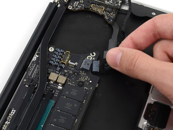
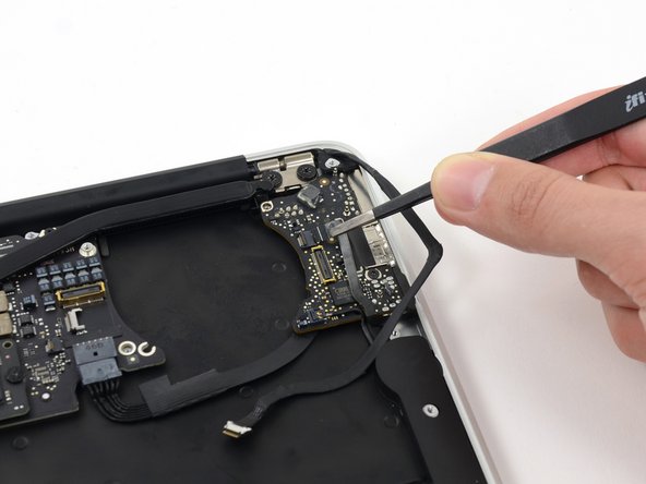
Disconnect the I/O board power cable from the logic board by pulling the cable out of its socket on the logic board.
-
-
이 단계는 번역되지 않았습니다. 번역을 도와주십시오
-
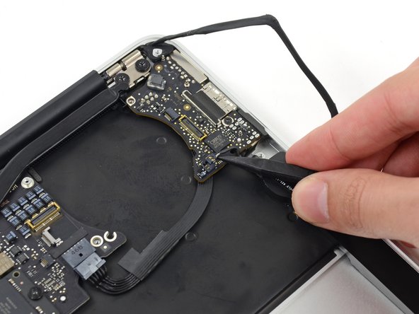
Use the tip of a spudger to carefully flip up the retaining flap on the microphone cable ZIF socket.
-
Pull the microphone ribbon cable straight out of its socket.
-
-
이 단계는 번역되지 않았습니다. 번역을 도와주십시오
-
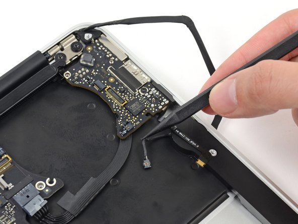
Use the tip of a spudger to pry under the speaker cable near the connector to lift the connector straight up out of its socket.
-
-
이 단계는 번역되지 않았습니다. 번역을 도와주십시오
-
Remove the small rubber gasket from the corner of the upper case nearest the I/O board.
-
-
이 단계는 번역되지 않았습니다. 번역을 도와주십시오
-
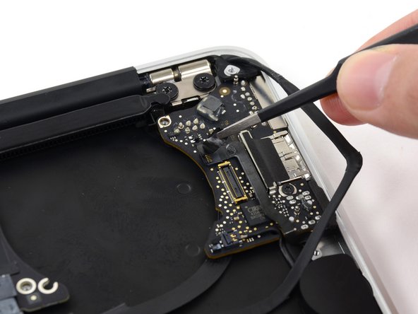
Remove the single 3.6 mm T5 Torx screw securing the I/O board to the upper case.
-
In some models this is a 3.1 mm T5 Torx screw.
-
-
이 단계는 번역되지 않았습니다. 번역을 도와주십시오
-
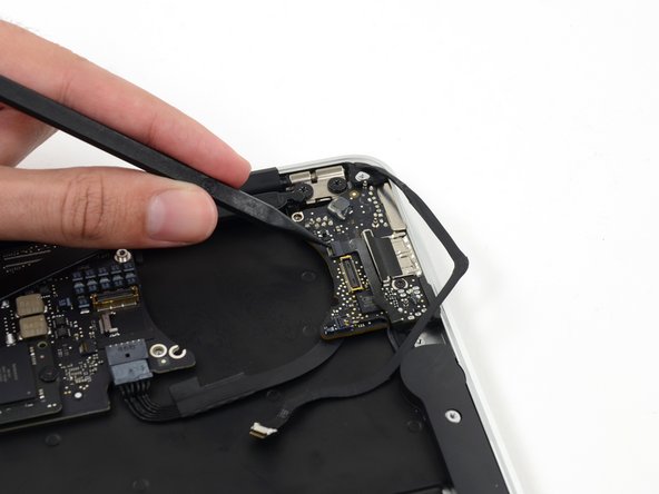
Carefully lift the I/O board by its power cable and pull it away from the edge of the case.
-


다른 11명이 해당 안내서를 완성하였습니다.

