이 버전에는 잘못된 편집 사항이 있을 수 있습니다. 최신 확인된 스냅샷으로 전환하십시오.
필요한 것
-
-
P5 펜타로브 드라이버를 사용하여 하난 케이스를 고정하는 다음 길이의 나사 10개를 풀어주세요:
-
9mm 나사 두 개
-
2.6mm 나사 여덟 개
-
-
이 단계는 번역되지 않았습니다. 번역을 도와주십시오
-
Use the flat end of a spudger to pry the I/O board cable connector up out of its socket on the I/O board.
-
-
이 단계는 번역되지 않았습니다. 번역을 도와주십시오
-
Carefully peel the I/O board cable from the adhesive securing it to the top of the fan.
-
-
이 단계는 번역되지 않았습니다. 번역을 도와주십시오
-
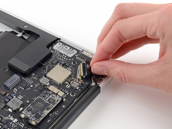
While gently pulling the I/O board cable upward near its connection to the logic board, use the flat end of a spudger to pry up on alternating sides of the connector to help "walk" it out of its socket.
-
Remove the I/O board cable.
-
-
이 단계는 번역되지 않았습니다. 번역을 도와주십시오
-
Use the tip of a spudger to carefully flip up the retaining flap on the fan cable ZIF socket.
-
-
이 단계는 번역되지 않았습니다. 번역을 도와주십시오
-
Remove the following three screws securing the fan to the upper case:
-
One 3.6 mm T5 Torx screw
-
One 2.7 mm T5 Torx screw
-
One 3.6 mm T5 Torx screw with a short head
-
-
이 단계는 번역되지 않았습니다. 번역을 도와주십시오
-
Lift the fan from the I/O board side and pull it free from the upper case.
-
Removing the fan will also disconnect the fan ribbon cable. Be careful not to snag it.
-
-
이 단계는 번역되지 않았습니다. 번역을 도와주십시오
-
Disconnect the I/O board by pulling its power cable away from its socket on the logic board.
-
-
이 단계는 번역되지 않았습니다. 번역을 도와주십시오
-
Use the flat end of a spudger to pry the left speaker cable connector up and out of its socket on the I/O board.
-
-
이 단계는 번역되지 않았습니다. 번역을 도와주십시오
-
Use the tip of a spudger to carefully flip up the retaining flap on the microphone ribbon cable ZIF socket.
-
-
-
이 단계는 번역되지 않았습니다. 번역을 도와주십시오
-
Remove the single 3.6 mm T5 Torx screw securing the I/O board to the upper case.
-
-
이 단계는 번역되지 않았습니다. 번역을 도와주십시오
-
Gently de-route the camera cable from its notch on the I/O board and push it out of the way with the tip of a spudger.
-
-
이 단계는 번역되지 않았습니다. 번역을 도와주십시오
-
Lift the I/O board from the logic board side and pull it free from the upper case.
-
Removing the I/O board will also disconnect the microphone ribbon cable. Be careful not to snag it.
-
-
이 단계는 번역되지 않았습니다. 번역을 도와주십시오
-
Remove the following five screws securing the battery to the upper case:
-
Three 6.3 mm T5 Torx screws
-
Two 2.4 mm T5 Torx screws
-
-
이 단계는 번역되지 않았습니다. 번역을 도와주십시오
-
Lift the battery from its edge nearest the logic board and remove it from the upper case.
-
-
이 단계는 번역되지 않았습니다. 번역을 도와주십시오
-
Grab the plastic pull tab secured to the display data cable lock and rotate it towards the top side of the computer.
-
-
이 단계는 번역되지 않았습니다. 번역을 도와주십시오
-
Use the flat end of a spudger to pry both antenna cable connectors up and off their sockets on the AirPort/Bluetooth card.
-
-
이 단계는 번역되지 않았습니다. 번역을 도와주십시오
-
Disconnect the camera cable connector with the tip of a spudger.
-
Pull the camera cable parallel to the face of the I/O board toward the front edge of the Air to disconnect it from its socket.
-
-
이 단계는 번역되지 않았습니다. 번역을 도와주십시오
-
Use the tip of a spudger or your fingernail to flip up the retaining flap on the trackpad ribbon cable ZIF socket.
-
Pull the trackpad ribbon cable straight out of its socket toward the front edge of the Air.
-
-
이 단계는 번역되지 않았습니다. 번역을 도와주십시오
-
Use the tip of a spudger to flip up the retaining flap on the keyboard backlight ribbon cable ZIF socket.
-
Use your spudger to gently pull the keyboard backlight ribbon cable out of its socket.
-
-
이 단계는 번역되지 않았습니다. 번역을 도와주십시오
-
Use the flat end of a spudger to pry the right speaker cable connector up and out of its socket on the logic board.
-
-
이 단계는 번역되지 않았습니다. 번역을 도와주십시오
-
Remove the six 6.3 mm T5 Torx screws securing the logic board to the upper case.
-
-
이 단계는 번역되지 않았습니다. 번역을 도와주십시오
-
Remove the inner two 4.9 mm T8 Torx screws securing the antenna cable retainer and left clutch hinge to the upper case.
-
-
이 단계는 번역되지 않았습니다. 번역을 도와주십시오
-
Push the antenna cable retainer away slightly and remove the 3 mm T5 Torx screw securing the end of the heat sink to the upper case.
-
-
이 단계는 번역되지 않았습니다. 번역을 도와주십시오
-
Slide the flat end of a spudger under the right speaker from the end nearest the hinge to the front edge of the Air to loosen the adhesive.
-
Remove the right speaker from the upper case.
-
-
이 단계는 번역되지 않았습니다. 번역을 도와주십시오
-
Carefully remove the logic board assembly from the upper case, minding any cables that may get caught.
-
Keep loose cables clear of the board so they aren't caught under it.
-
Make sure the antenna cables are inserted into their respective notches, as highlighted in the second picture.
-
-
이 단계는 번역되지 않았습니다. 번역을 도와주십시오
-
Remove the single 2.85 mm T5 Torx screw securing the SSD to the logic board.
-
-
이 단계는 번역되지 않았습니다. 번역을 도와주십시오
-
Pull the drive straight out of its socket and remove it from the logic board.
-
-
이 단계는 번역되지 않았습니다. 번역을 도와주십시오
-
Remove the single 2.9 mm T5 Torx screw securing the AirPort/Bluetooth board to the logic board.
-
-
이 단계는 번역되지 않았습니다. 번역을 도와주십시오
-
Slightly lift the free end of the AirPort/Bluetooth board and pull it out of its socket on the logic board.
-
Remove the AirPort/Bluetooth board from the logic board.
-
-
이 단계는 번역되지 않았습니다. 번역을 도와주십시오
-
Remove the four 2.5 mm T5 Torx screws securing the heat sink to the logic board.
-
-
이 단계는 번역되지 않았습니다. 번역을 도와주십시오
-
Make sure the antenna cables are inserted into their respective notches on the logic board, as highlighted in the last picture.
-


다른 12명이 해당 안내서를 완성하였습니다.

댓글 2개
Can you use an 2017 logic board onto a MacBook Air 2014 “body” (13”)? Airs from 2013 to 2017 seems to be aboud the same CPU and all others parts are the sam also.
Do you have any video of this case working?