소개
Replace a broken right clutch hinge to keep your display opening smoothly.
필요한 것
-
-
Unscrew the three evenly-spaced Phillips screws from along the rear wall of the battery compartment.
-
-
-
Remove the following 3 screws:
-
One 11 mm Phillips#00 in the middle of the lower case. (Head: 5mm dia. x .75mm thick)
-
Two 14.5 mm Phillips #00 (Head: 5mm dia. x .75mm thick)
-
-
-
Grasp the white plastic tab attached to the hard drive and pull it to the left, removing the hard drive from the computer.
-
-
-
-
Remove the 2 mm Phillips #00 screw securing the rear corner of the optical drive.
-
The silver-jacketed Bluetooth cable may be covering the screw. If so, carefully push it aside. You may need to remove the screw holding the ground shield lugs for the two nearby cables before you can move the Bluetooth cable aside sufficiently. This screw is 7mm in earlier models, and may be 4.2mm in Santa Rosa/Penryn and 2009 models.
-
-
-
Lift the side of the optical drive closest to you, then slide the drive towards you, and up and out of the computer.
-
First, slide its side nearest to the rear of the Macbook under the edge of the rear frame to the left of the hinge, while also sliding the optical drive's mounting tab at its upper left corner under the cables at this location.
-
Lower the drive partially into the lower housing. Keep the hard drive cable away from the optical drive bay.
-
Before dropping the drive fully in place, use a spudger to push forward (towards the front of the drive) on the screw hole in the drive's mounting tab.
-
Push forward the slider, which runs along the far side of the drive, to insert the end of this slider into a small channel in the lower case's frame. This helps hold the drive in place.
-
-
-
For original Macbook Core Duo and Core 2 Duo models, remove these 3 screws:
-
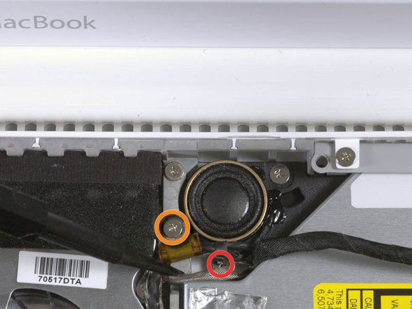
Two 3 mm Phillips near the right speaker.
-
One 6 mm Phillips threaded through a hole in a plastic finger above the subwoofer.
-
For Santa Rosa/Penryn and 2009 models, which don't have a c-channel:
-
Remove only the single 3 mm Phillips screw from the right speaker, and skip step 26.
-
-
-
Use a spudger to carefully disconnect the microphone cable from the logic board. You'll want to work from side to side, and slowly wiggle the plug back and out of its socket.
-
-
-
Disconnect the antenna cables from the Airport card:
-
If you have an original MacBook Core Duo or Core 2 Duo model, see the first picture, which shows that there are three antenna cables.
-
If you have a MacBook Core 2 Duo Santa Rosa/Penryn or 2009 model, there are only two antenna cables, and the plug/socket for the black inverter cable is in a different location. There may be a square foam piece over the plug/socket for the inverter board connector.
-
Disconnect the inverter cable from its socket by inserting a spudger between the right or left ends of the plug and the socket, and prying gently vertically. Do NOT pry up on the socket--you must pull up on the plug alone, vertically out of the socket. Do not pull in the direction of the cable wires or you will tear the socket off the logic board.
-
-
-
For original Macbook Core Duo and Core 2 Duo models, see first picture and remove the following 2 screws from the right hinge mount:
-
One 6 mm Phillips on the left side of the hinge mount.
-
One 10 mm Phillips on the right side of the hinge mount.
-
For Santa Rosa/Penryn and 2009 models, see second picture and remove the following 3 screws from the right hinge mount:
-
One 3 mm smalller diameter Phillips on the far left.
-
One 5.2 mm larger diameter, 4.2 mm head Phillips in the middle.
-
One 10 mm larger diameter, 4.2mm head Phillips from the far right.
-
Before removing the right hinge mount, take care to see how its pieces fit together, including the small white plastic piece. Knowing how the mount pieces fit together will help with reassembly. Lift the right hinge mount with the small white plastic piece out of the computer.
-
-
-
Hold the display with one hand while removing the following 3 screws from the left hinge mount:
-
One 7.2 mm smaller diameter Phillips from the right side.
-
One 5.2 mm larger diameter Phillips from the middle.
-
One larger diameter 10 mm Phillips from the left side.
-
Lift the left hinge mount with white plastic piece out of the computer.
-
Check that the cables coming out of the right end of the left hinge are not trapped under other cables.
-
-
-
Use a thin plastic card to release the tabs and their clips holding the front display bezel to the display assembly. There are five tabs along the left side of the display bezel.
-
-
-
While holding the display down with one hand, use your other hand to lift the left end of the clutch cover off the clutch hinge and guide the inverter cable and AirPort cables through the gap in the clutch cover. If the cables snag on the two hooked tabs on the inside end of the clutch cover, free them carefully.
-
-
-
Remove the small piece of foam tape stuck down above each of the bezel covers, at the lower left and right corners.
-
-
-
Remove the three 3.2 mm Phillips screws securing the right clutch hinge to the rear display bezel.
-


To reassemble your device, follow these instructions in reverse order.
To reassemble your device, follow these instructions in reverse order.
다른 19명이 해당 안내서를 완성하였습니다.

댓글 한 개
This guide was amazing! I was able to successfully take apart and put together my computer without any issues. However there is a video online which I highly recommend you watch in addition to reading this guide, it just makes this process so much easier.
"The Apple 13" Macbook Disassembly & Repair Guide" by 8-bit-guy https://www.youtube.com/watch?v=PEnCD93r...
While on step #6 of putting my laptop back together, I foolishly tried to tilt my laptop so that the screw hole was facing me, and the center screw got sucked into the magnetic vortex, never to be found again. So don't do that.
After taking apart my computer, I discovered that I needed a new Left Clutch Hinge, Rear Display Bezel and Clutch Cover. However, as parts cannot be shipped to my location, I fixed my computer by super-gluing (should have used epoxy 2 ton glue) the broken Clutch Hinges to the Rear Display Bezel and duct-taping the Clutch Cover to the metal frame around the LCD panel as well as the back of the Rear Display Bezel.