주요 콘텐츠로 건너뛰기

이 버전에는 잘못된 편집 사항이 있을 수 있습니다. 최신 확인된 스냅샷으로 전환하십시오.

필요한 것

  1. , 하단 케이스: 1 단계, 이미지 1/1
    이 단계에 사용된 도구:
    Magnetic Project Mat
    $19.95
    구매
    • 하단 케이스를 상단 케이스에 고정하는 다음 나사 열 개를 풀어주세요:

    • 2.3mm P5 Pentalobe/펜타로브/별나사 두 개

    • 3.0mm P5 Pentalobe/펜타로브/별나사 여덟 개

    • 이 수리를 하는 동안 각 나사를 기억하고 기기 손상을 방지하기 위해 원래 위치로 정확히 돌아가는 것을 확인하세요.

  2. : 2 단계, 이미지 1/1
    • 상단 케이스와 하단 케이스 사이에 손가락을 끼워 넣으세요.

    • 상단 케이스에서 하단 케이스를 조심히 당기세요.

    • 하단 케이스를 분리하고 옆에 놓아두세요.

  3. : 3 단계, 이미지 1/3 : 3 단계, 이미지 2/3 : 3 단계, 이미지 3/3
    • 하단 케이스는 플라스틱 클립 두 개로 상단 케이스 중앙에 연결되어 있습니다.

    • 재조립하는 동안 하단 케이스 중앙을 살살 눌러 플라스틱 클립 두 개를 다시 부착하세요.

  4. , 배터리 커넥터: 4 단계, 이미지 1/1
    • 배터리 접촉 보드에 붙어있는 플라스틱 커버를 분리하세요.

  5. : 5 단계, 이미지 1/1
    • 배터리 커넥터 보드를 로직 보드에 고정하는 다음 나사들을 풀어주세요:

    • 2.8mm T6 Torx/톡스 나사 두 개

    • 7.0mm T6 Torx/톡스 어깨 나사 한 개

  6. : 6 단계, 이미지 1/2 : 6 단계, 이미지 2/2
    • 핀셋을 사용하여 배터리 커넥터 보드의 오른쪽 하단 근처의 작은 플라스틱 덮개를 분리하세요.

  7. : 7 단계, 이미지 1/1
    • 배터리 커넥터를 로직 보드 어셈블리에 고정하는 와이드 헤드 6.4mm T6 Torx/톡스 나사를 풀어주세요.

  8. : 8 단계, 이미지 1/2 : 8 단계, 이미지 2/2
    • 로직 보드에서 배터리 커넥터 보드를 조심히 들어올리세요.

    • 배터리 케이블을 약간 구부려서 보드를 로직 보드 위에 매달아 방해하지 않도록 하는 것이 좋습니다.

    • 보드를 완전히 접거나 케이블을 주름잡지 마세요. 배터리를 손상할 수 있습니다.

  9. , 배터리 접속 보드: 9 단계, 이미지 1/2 , 배터리 접속 보드: 9 단계, 이미지 2/2
    • 핀셋으로 인터포저를 잡으세요.

    • 인터포저는 하나의 전기 연결을 다른 전기 연결과 연결하는 인터페이스 이름입니다. 이 수리에서는 배터리를 로직 보드에 연결하는 보드입니다.

    • 인터포저를 로직 보드에서 들어 올려 분리하세요.

    • 이 보드를 분리하는 것은 수리하는 동안 배터리 분리 상태를 유지하여 실수로 컴퓨터 전원이 켜지는 것을 방지할 수 있습니다. 또한 보드가 예기치 않게 떨어져 나오지 않도록 미리 꺼내는 것도 좋은 생각입니다.

  10. 이 단계는 번역되지 않았습니다. 번역을 도와주십시오

    : 10 단계, 이미지 1/1
    • Remove the following screws securing the heat sink to the logic board assembly:

    • One 2.4 mm Phillips #00 screw

    • One 3.4 mm T5 Torx screw

    • Four 2.7 mm T5 Torx screws

  11. 이 단계는 번역되지 않았습니다. 번역을 도와주십시오

    : 11 단계, 이미지 1/2 : 11 단계, 이미지 2/2
    • Lift and remove the heat sink up off the logic board assembly.

    • When reinstalling the heat sink, be sure to apply a new layer of thermal paste. If you have never applied thermal paste before, we have a guide that makes it easy.

  12. 이 단계는 번역되지 않았습니다. 번역을 도와주십시오

    : 12 단계, 이미지 1/2 : 12 단계, 이미지 2/2
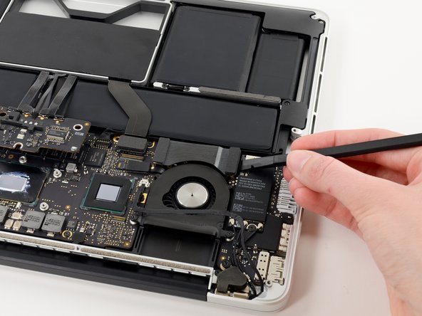
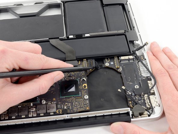
    • Use the flat end of a spudger to pry the right side of the I/O board data cable connector up off its socket on the I/O board.

    • When prying the I/O board data cable connector from its socket, make sure to pry the connector itself and not the socket. Prying the socket may cause irreversible damage to the I/O board.

  13. 이 단계는 번역되지 않았습니다. 번역을 도와주십시오

    : 13 단계, 이미지 1/2 : 13 단계, 이미지 2/2
    • Wedge the flat end of a spudger beneath the left side of the I/O board data cable connector.

    • Gently twist the spudger to disconnect the I/O board data cable connector from its socket on the logic board.

  14. 이 단계는 번역되지 않았습니다. 번역을 도와주십시오

    : 14 단계, 이미지 1/1
    • Lift and remove the I/O board data cable from the MacBook Pro.

  15. 이 단계는 번역되지 않았습니다. 번역을 도와주십시오

    : 15 단계, 이미지 1/3 : 15 단계, 이미지 2/3 : 15 단계, 이미지 3/3
    • Use the tip of a spudger to flip up the retaining flap on the right fan ribbon cable ZIF socket.

    • Be sure you are prying up on the hinged retaining flap, not the socket itself.

    • Pull the right fan ribbon cable straight out of its socket on the logic board.

  16. 이 단계는 번역되지 않았습니다. 번역을 도와주십시오

    : 16 단계, 이미지 1/1
    • Remove the three 3.1 mm T5 Torx screws securing the right fan to the logic board assembly.

  17. 이 단계는 번역되지 않았습니다. 번역을 도와주십시오

    : 17 단계, 이미지 1/1
    • Lift and remove the right fan out of the upper case.

  18. 이 단계는 번역되지 않았습니다. 번역을 도와주십시오

    : 18 단계, 이미지 1/1
    • Remove the single 2.7 mm T5 Torx screw securing the AirPort board to the I/O board.

  19. 이 단계는 번역되지 않았습니다. 번역을 도와주십시오

    : 19 단계, 이미지 1/3 : 19 단계, 이미지 2/3 : 19 단계, 이미지 3/3
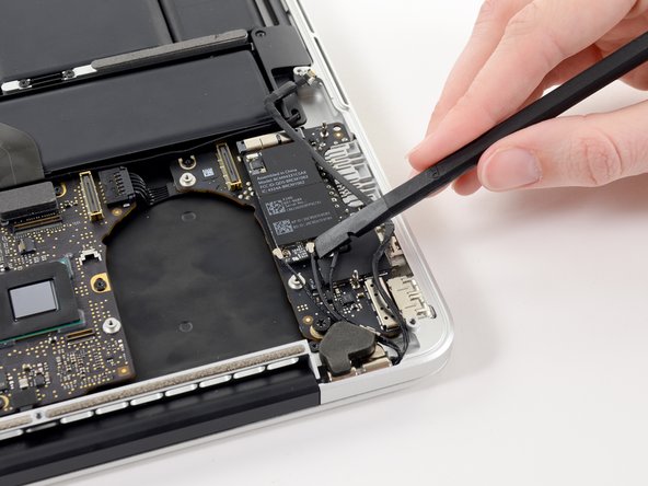
    • Use the flat end of a spudger to pry and disconnect the three antenna cable connectors from the AirPort board.

    • The three cables are coded with black sleeves of different lengths. During reassembly:

    • Connect the long-sleeved cable to the center socket.

    • The short-sleeved cable connects next to the screw.

    • The remaining cable has no sleeve, and connects in the last empty socket, next to the fan.

  20. 이 단계는 번역되지 않았습니다. 번역을 도와주십시오

    : 20 단계, 이미지 1/2 : 20 단계, 이미지 2/2
    • Move the antenna cables aside, clear of the AirPort board.

  21. 이 단계는 번역되지 않았습니다. 번역을 도와주십시오

    : 21 단계, 이미지 1/2 : 21 단계, 이미지 2/2
    • Pull the AirPort board straight out of its socket on the I/O board.

  22. 이 단계는 번역되지 않았습니다. 번역을 도와주십시오

    : 22 단계, 이미지 1/2 : 22 단계, 이미지 2/2
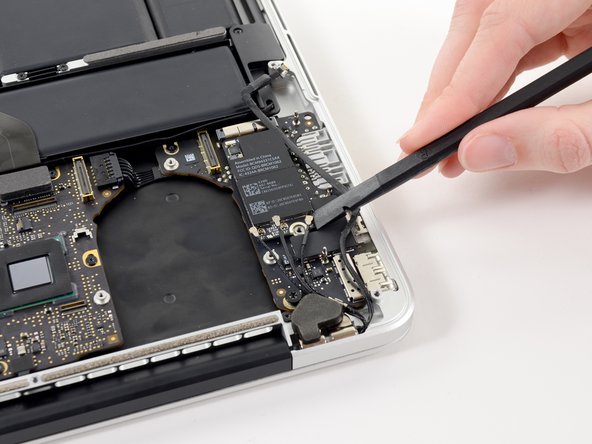
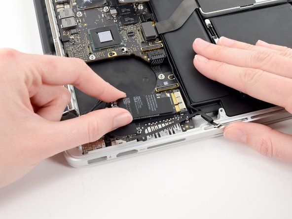
    • Use the tip of a spudger to push the edges of the I/O board power connector straight out of its socket on the logic board.

    • It is recommended to carefully push on both sides of the connector to "walk" it out of its socket.

  23. 이 단계는 번역되지 않았습니다. 번역을 도와주십시오

    : 23 단계, 이미지 1/1
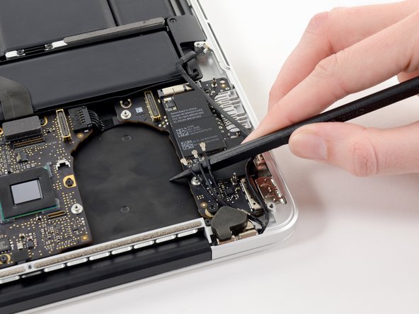
    • Pull the I/O board connector straight out of its socket on the logic board.

  24. 이 단계는 번역되지 않았습니다. 번역을 도와주십시오

    : 24 단계, 이미지 1/1
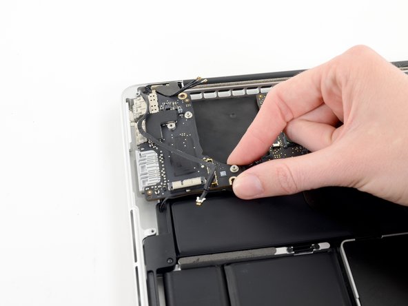
    • Remove the following two screws securing the I/O board to the upper case:

    • One 3.5 mm T5 Torx screw

    • One 4.9 mm T8 Torx screw

  25. 이 단계는 번역되지 않았습니다. 번역을 도와주십시오

    : 25 단계, 이미지 1/2 : 25 단계, 이미지 2/2
    • Carefully pull and remove the I/O board away from its recess in the upper case.

결승점

다른 2명이 해당 안내서를 완성하였습니다.

Sam Goldheart

회원 가입일: 10/18/12

465,611 평판

안내서 538개 작성하였습니다

iFixit iFixit 회원

Staff

135 회원들

안내서 16,731개 작성하였습니다

댓글 0개

댓글 쓰기

조회 통계:

24 시간 전: 2

7일 전: 5

30일 전: 15

전체 시간: 4,418