이 버전에는 잘못된 편집 사항이 있을 수 있습니다. 최신 확인된 스냅샷으로 전환하십시오.
필요한 것
-
-
하단 케이스를 MacBook Pro 13" Unibody에 고정하는 다음 나사 열 개를 풀어주세요:
-
3mm 십자 나사 일곱 개
-
13.5mm 십자 나사 세 개.
-
-
이 단계는 번역되지 않았습니다. 번역을 도와주십시오
-
Use a spudger to pry up the fan connector out of its socket on the logic board.
-
-
이 단계는 번역되지 않았습니다. 번역을 도와주십시오
-
Remove the following three screws:
-
One 7 mm T6 Torx screw
-
Two 5.4 mm T6 Torx screws
-
-
이 단계는 번역되지 않았습니다. 번역을 도와주십시오
-
Grab the plastic pull tab secured to the display data cable lock and rotate it toward the DC-In side of the computer.
-
Gently pull the display data cable connector away parallel to the board.
-
-
이 단계는 번역되지 않았습니다. 번역을 도와주십시오
-
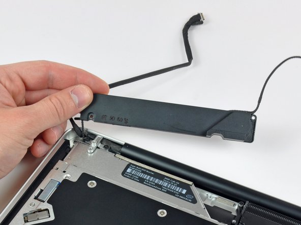
Remove the following two screws securing the display data cable bracket to the upper case:
-
One 8.6 mm Phillips
-
One 5.6 mm Phillips
-
Lift the display data cable bracket out of the upper case.
-
-
이 단계는 번역되지 않았습니다. 번역을 도와주십시오
-
Use the flat end of a spudger to pry the subwoofer and right speaker connector up off the logic board.
-
-
이 단계는 번역되지 않았습니다. 번역을 도와주십시오
-
Pull the camera cable connector toward the optical drive to disconnect it from the logic board.
-
-
이 단계는 번역되지 않았습니다. 번역을 도와주십시오
-
Use the flat end of a spudger to pry the optical drive, hard drive, and trackpad cable connectors up off the logic board.
-
-
-
이 단계는 번역되지 않았습니다. 번역을 도와주십시오
-
Use your fingernail or the tip of a spudger to flip up the cable retaining flap on the ZIF socket for the keyboard ribbon cable.
-
Use your spudger to slide the keyboard ribbon cable out of its socket.
-
-
이 단계는 번역되지 않았습니다. 번역을 도와주십시오
-
Peel the small strip of black tape off the keyboard backlight ribbon cable socket.
-
-
이 단계는 번역되지 않았습니다. 번역을 도와주십시오
-
Use the tip of a spudger to flip up the cable retaining flap on the ZIF socket for the keyboard backlight ribbon cable.
-
Use your spudger to slide the keyboard backlight ribbon cable out of its socket.
-
-
이 단계는 번역되지 않았습니다. 번역을 도와주십시오
-
Use the flat end of a spudger to pry the battery indicator cable connector up off the logic board.
-
-
이 단계는 번역되지 않았습니다. 번역을 도와주십시오
-
Use the tip of a spudger to pry the microphone off the adhesive attaching it to the upper case.
-
-
이 단계는 번역되지 않았습니다. 번역을 도와주십시오
-
Remove the following screws:
-
Two 7 mm T6 Torx screws from the DC-In board
-
Five 3.3 mm T6 Torx screws
-
Two 4 mm T6 Torx screws
-
-
이 단계는 번역되지 않았습니다. 번역을 도와주십시오
-
Remove the following Tri-point screws securing the battery to the upper case:
-
One 5.5 mm Tri-point screw
-
One 13.5 mm Tri-point screw
-
Lift the battery out of the upper case.
-
-
이 단계는 번역되지 않았습니다. 번역을 도와주십시오
-
Lift the logic board from its left edge and raise it until the ports clear the side of the upper case.
-
Pull the logic board away from the side of the upper case and remove it, minding the DC-In board that may get caught.
-
-
이 단계는 번역되지 않았습니다. 번역을 도와주십시오
-
Remove the soft padding that may be on top and gently pull the connector up out of its socket on the logic board.
-
-
이 단계는 번역되지 않았습니다. 번역을 도와주십시오
-
Pull the camera cable connector toward the optical drive to disconnect it from the logic board.
-
-
이 단계는 번역되지 않았습니다. 번역을 도와주십시오
-
Use the flat end of a spudger to pry the optical drive connector straight up off the logic board.
-
-
이 단계는 번역되지 않았습니다. 번역을 도와주십시오
-
Use the flat end of a spudger to pry the hard drive connector straight up off the logic board.
-
-
이 단계는 번역되지 않았습니다. 번역을 도와주십시오
-
Remove the following screws securing the subwoofer to the upper case:
-
One 3.8 mm Phillips screw
-
One 5 mm Phillips screw
-
-
이 단계는 번역되지 않았습니다. 번역을 도와주십시오
-
Lift the subwoofer off the optical drive, and set it above the computer.
-
-
이 단계는 번역되지 않았습니다. 번역을 도와주십시오
-
Remove the two 10 mm Phillips screws securing the camera cable bracket to the upper case.
-
Lift the camera cable bracket out of the upper case.
-
-
이 단계는 번역되지 않았습니다. 번역을 도와주십시오
-
Remove the three 2.5 mm Phillips screws securing the optical drive to the upper case.
-
Lift the optical drive from its right edge and pull it out of the computer.
-
-
이 단계는 번역되지 않았습니다. 번역을 도와주십시오
-
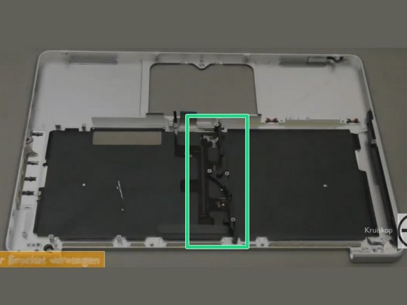
Remove the 10mm phillips #00 screw.
-
Remove the 5mm phillips #00 screw.
-
Remove and set aside the centre bracket.
-
-
이 단계는 번역되지 않았습니다. 번역을 도와주십시오
-
Carefully peel the black keyboard backlight from the upper case and remove it.
-
Slide a spudger under the bottom right corner and slide the spudger up the right hand side of the backlight.
-
Once you have the right hand side of the backlight loose, you can then use your fingers to gently peel the backlight from the keyboard.
-
-
이 단계는 번역되지 않았습니다. 번역을 도와주십시오
-
Remove the following screws:
-
Two 3 mm PH00 screws from the power button.
-
Sixty-seven 2mm PH000 screws from the keyboard.
-
Gently lift out the keyboard (and the attached power button).
-


다른 169명이 해당 안내서를 완성하였습니다.

팀

댓글 60개
Having just done this - successfully, I might add - I need to make this guide a little more clear:
Step 1: open the case. See every other tear down for the screw count.
Step 1A: remove the battery connection.
Step 2/3: remove the fan as instructed.
Step 3A: remove the optical drive. See the relevant tear down guide for specifics.
Step 3B: remove all of the connecters to the logic board: keyboard, backlight, trackpad, fan, speaker/subwoofer, battery status indicator, hard drive, optical drive, camera, display. See the logic board removal guide for more info.
Step 3C: remove the screws holding the DC-in board and the logic board. Remove the logic board.
The remaining steps are pretty OK. Buy a new backlight and diffuser panel along with your new KB.
This guide is not very good at all... terrible actually. It misses so many steps!
mark -
I successfully completed this yesterday. Having never done Mac repairs myself the difficulty level made me nervous, however don't be afraid to give it a go! There are lots of little screws and parts but its not hard, more fiddly.
In addition to the tools here consider getting some kind of segmented box or little containers to keep all the screws separate. Also when I opened it up my logic board was filthy with dust! Keep a microfiber cloth and perhaps a soft brush around the clean a little as you go.
Where do you purchase the 13" Macbook / Macbook Pro (2009-2012) Keyboard? I can see the uppercase is for sale, but the guide is for just replacing the keyboard.
Rob Meidal - 답글
Keyboards can be purchased from powerbookmedic, thebookyard, ebay and aliexpress.
David Fear - 답글