소개
By following this guide, you can install a high-definition LCD panel on your MacBook Pro!
필요한 것
-
-
Use your fingers to push both battery release tabs away from the battery, and lift the battery out of the computer.
-
-
-
Remove the two Phillips screws in the battery compartment near the latch.
Getting these screws in and out is difficult because most screwdrivers are longer then the battery compartment is deep and so will be slightly off plumb. When you go to re-assemble the computer, getting these screws to seat is one of the hardest parts of the re-assembly. It's very important to be gentle and not to strip the threads.The screw should tighten and come to a stop after 3-4 turns. If you turn 6 or more turns and don't feel it grab, then back off and try again, making sure that everything is in alignment.It might be easier to start with the left screw, because it is further away from the latch mechanism.
-
-
-
Remove the four Phillips screws on the port side of the computer.
Be careful when reassembling your laptop -- do not put the screw into the DVI port! It will not come out.
Scott Rose - 답글
Been there, done that!
I honestly don't remember how did I ultimately succeeded in getting that %#*@ screw back from the hole...by Scott Rose Jan 4 @ 11:12 PM
Be careful when reassembling your laptop -- do not put the screw into the DVI port! It will not come out.
To keep this from possibly happening, I placed 2 pieces of tape over the DVI connector pin holes.
Be careful in step 4, these two screws are shorter than the four screws in step 6, dont mix them up!
-
-
-
Lift up at the rear of the case and work your fingers along the sides, freeing the case as you go. Once you have freed the sides, you may need to rock the case up and down to free the front of the upper case. This stage can be quite tricky. Over the DVD reader are 4 tabs set back which pull out vertically.
-
Note that the two small tongues on the left hand front of the upper case may bend while you remove the upper case. When re-installing, you may need to bend them back to fit in the grooves in the lower case.
khank로 부터 인용:
On my MacBook, there were no pushbuttons. Rather, two mini phillips screws were holding the case on inside the battery bay. The two screws are under two ball-bearing-like nubs that help hold the battery in the bay.
I just realized these were the screws mentioned in Step 4, which I missed originally. Did you miss step 4 too?
I discovered that I didn't need to take the case off completely. I just propped it up with a small screwdriver and was able to remove the airport card and replace it with a new one fairly easily.
That's not so difficult step. you shoul know , that front edge of upper case holding only on 5 plastic "locks" 4 in front edge upon the superdrive, 5-th near the "sleep light, open laptop button"
just lift up the rear edges of upper case to 35-40 degrees
Archhawk로 부터 인용:
Getting the top case off, especially right above the optical drive slot was a @#$%^. !^$%. Was finally able to work it loose by twisting in the budger. Be careful.
I agree! It was really very difficult just ROCKING the front panel. NOT done! Do not pry it from the front of the unit, as the soft metal edge gets scratched! I turned the unit upside down and slowly pried the keyboard apart left-to-right from INSIDE the Battery Bay, slipping a plastic pen to keep it apart. When I finally looked at what was holding it down, it was these 5 grey&black plastic SNAP slots, and 4 of them were behind the DVD slot.
I found I had to push with a little force from underneath the battery compartment where the touch pad is located to free the bottom edge of the case. The case came away with two loud snaps. At first I thought I'd broken something, but then it appeared that it was just the plastic above the slot loading super drive that was held in very tightly and needed some encouragement.
Joshua May - 답글
There are several clips along the front of the case in front of trackpad and above the optical drive slot. These need to be gently levered open (eg using an old credit card), and clipped closed on reassembly. Start at the left hand side. Take care not to bend the aluminum top. When reassembling, check the top panel for kinks/bends and straighten by hand before reassembly.
The way I did it was to lift the back to about 45% (the ribbon cable is long enough) and then used the spudger to force the 4 snap tabs in front of the optical drive to separate, working from the right edge towards the middle (they will 'pop'), ending with the last tab to the left of the sleep light.
After reading all the step 9 comments I was prepared for it to be very difficult. The two bendable tabs on the left front of the case were no bigger than 1/4 inch wide each and caused no trouble taking it off or putting it back on. Lifting the cover off happened before I knew it. I was carefully lifting the cover from side to side and 'poof' it was off and the yellow ribbon attaching between the case and the keyboard was so old and brittle it parted ways without my permission so that took care of step 10 right there but no problem.
Being prepared, reading the guide, printing the guide, taping each screw to the right place on the guide made it all easy. I'm amazed it went so smooth on the first run-through. Thanks iFixit!
-
-
-
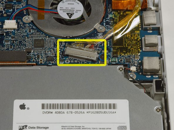
Disconnect the trackpad and keyboard ribbon cable from the logic board, removing tape as necessary.
-
Remove the upper case.
not necessary. just attach a string around both the screen and the keyboard. it will stay in a steady position..
-urdus.
I found that the ribbon connecting the top part of the case to the logic board wasn't long enough and the connector did have to be disconnected.
urdus로 부터 인용:
not necessary. just attach a string around both the screen and the keyboard. it will stay in a steady position..
-urdus.
Excellent tip! Thanks, this allowed me to skip steps 10 and 11 (any unnecessary tinkering with the logic board is recommended).
-
-
-
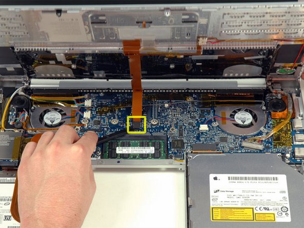
Deroute the Airport antenna cables from their channel in the left speaker.
-
-
-
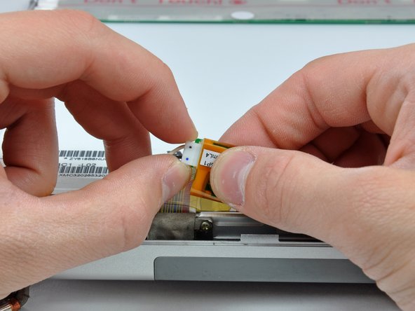
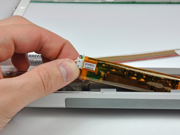
Disconnect the iSight, inverter, and left fan cables from the logic board by gently pulling in the direction of each cable.
-
-
-
-
Remove the two 5 mm Phillips screws from the lower left and right corners of the display (two screws total).
The screw fixing points on my MBP came away from the back case. They are spot welded to the back case and in the Photo's I have you can see the point's each. You may think that if this happens you lose the ability to use the screws to secure the enclosure but you still can use the screws if you position the fixing points before clipping the front panel in place. Have a needle of small nail to align though the holes before replacing the screws. This is not easy and you need to be practices at this sort of repair.
They sit under the plastic surround and do! add the the string of the completed enclosure.
-
-
-
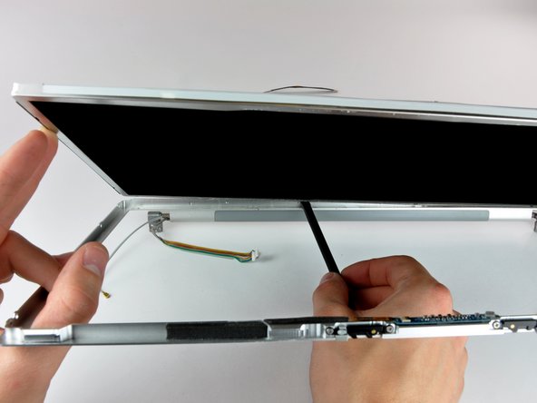
Insert the flat end of a spudger perpendicular to the face of the display between the plastic strip attached to the rear bezel and the front bezel.
-
With the spudger still inserted, rotate it away from the display to separate the front and rear bezels.
-
Work along the left edge of the display until the rear bezel is evenly separated from the front bezel.
-
-
-
Insert the flat end of a spudger perpendicular to the face of the display between the plastic strip attached to the rear bezel and the front bezel.
-
With the spudger still inserted, rotate it away from the display to separate the front and rear bezels.
-
Work along the right edge of the display until the rear bezel is evenly separated from the front bezel.
-
-
-
Insert the flat end of a spudger between the front bezel and the plastic strip attached to the rear bezel near the screw holes at the bottom corners of the display.
-
Rotate your spudger toward the rear bezel to separate it from the front bezel.
-
If necessary, enlarge the gap between the lower edge of the rear bezel and the clutch cover until the two components are completely separated.
-
-
-
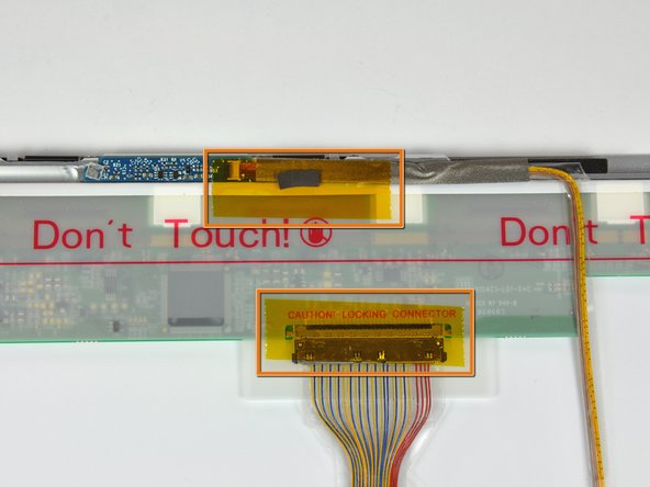
Remove the pieces of yellow kapton tape from the bottom left corner of the display.
-
Remove the pieces of tape securing the display data cable and camera cable to the display.
-
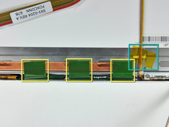
Peel the three green antenna ground straps off the copper tape along the bottom edge of the LCD.
-
Remove the piece of tape securing the camera cable to the LCD.
mine also. Does anyone know the function of these? They're called ground straps here, so I would guess they should have good contact, but how do you get them to adhere again? I replaced my inverter but the screen is still dark. I think worse than before, since before, it would blink and sometimes work for an instant. I'm going to go back in and check my connectors and such, but was trying to gather more info. Any thoughts to share anyone?
-
-
-
Use the flat end of a spudger to gently lift one of the top corners of the LCD out of the front bezel.
Same here, needed a heat gun. P.S. Harbor Freight had them on sale cheap (tip, not advertisement).
This is easy if you use the small lugholes on the left and right sides near the top edge (which cover philips screws) to insert a spudger or fine slotted screwdriver and then work along the top with another spudger as if you were using tyre levers on a bicycle tyre. when you get to the middle, repeat from the other side.
-
-
-
Work your way along the top edge of the LCD, slowly prying the attached steel strip away from the front bezel.
Push the spunger gradually along the gap between screen and rear bezel. Dont use a back and forth motion to prize them apart, as is suggested in earlier steps. I initially tried using a back and forth motion to prize them apart which slightly bent the rear bezel.
-
-
-
Now that the top edge is free, slightly lift the LCD out of the front bezel for enough room to pry the steel strip along the lower edge of the LCD away from the front bezel.
-
Pry along the lower edge of the LCD until it is freed from the adhesive on the front bezel.
Prying with plastic spudger at the lower edge of the display housing bent the aluminum frame for me. Suggestion: if you don't plan on keeping the old glass, pry it away from the aluminum slowly (opposite direction than shown in step 33).
-
-
-
Lift the LCD out of the front bezel, minding any cables that may get caught.
I finally finished this, it took a few hours. After I finally got the LCD separated from the bezel, I got the replacement screen out of the box ready to install and I couldn't believe I had been sent the wrong part (NOT ORDERED FROM THIS WEBSITE!!). Anyway I thought I would put everything back together until the correct part arrived...I turned the computer on and the screen was fixed...no new part required. Now I am thinking that maybe the screen wasn't stuffed but maybe a connector was loose.......anyway these instructions were a godsend and next time i am ordering my part from here.
-
-
-
Reconnect the following connectors back in their respective sockets on the logic board:
-
Camera connector cable
-
Inverter cable
-
Left fan
-
Display data cable
I have performed this repair with the standard resolution display (though I went with the glossy instead of the matte which came with my MBP) and at one point when I was re-assembling the display assembly a screw came loose and cracked the new lcd from the back. I have been living with my mistake since :)
Now with the possibility of upgrading to HD, I'm wondering if anyone can help me source the right part...google has not been my friend on this search so any tips, riddles, or haiku would be most helpful. Thanks!
-
-
-
Connect an external USB mouse to your MacBook Pro.
-
Power up the MacBook Pro and boot into the OS.
-
Carefully lift the upper case and use a spudger to pry the trackpad/keyboard ribbon cable up off the logic board. Remove the upper case from the computer.
-
Use your external mouse to select the "Sleep" option from the Apple menu.
-
Make sure that the sleep light is pulsing before continuing.
-


To reassemble your device, follow these instructions in reverse order.
To reassemble your device, follow these instructions in reverse order.
다른 6명이 해당 안내서를 완성하였습니다.

Before beginning, I found some small plastic bags and labeled each of the with the location the screws would come from once removed and the appropriate step number. Once the screws were removed I placed them in the labeled bags and did not have to worry about mixing screws up. Also, provided a good way to insure that no steps were skipped in the reverse process
rpbetancourt - 답글
If you don't have any plastic bags, you can always print out the photos in black and white as you go, and then tape the screws on to the print outs over the circles that denote the screw positions in the photos. This method helps get every single screw back in it's exact location, even months after a tear down. ;o)
Adam - 답글
Thank you very much!
Evgeniy - 답글
When I did this, I used a empty egg carton to store my screws. I wrote the steps where I removed screens in Sharpie on the bottom of the "egg cup" and then dropped the screws in as I went. Then I just worked backwards to put it all back together.
mark93 - 답글
I Generally just use a piece of paper with a rough sketch of the system and locations of the screws with prestik.
Tarn Alcock - 답글