이 버전에는 잘못된 편집 사항이 있을 수 있습니다. 최신 확인된 스냅샷으로 전환하십시오.
필요한 것
-
이 단계는 번역되지 않았습니다. 번역을 도와주십시오
-
Use the flat end of a spudger to pry the rubber hinge covers up off the left and right hinges.
-
-
-
스퍼저의 납작한 끝을 사용하여 로직 보드의 소켓에서 I/O 보드 커넥터를 똑바로 들어 올립니다.
-
비슷한 방법으로 I/O 보드의 소켓에서 I/O 보드 케이블 커넥터를 분리하세요.
-
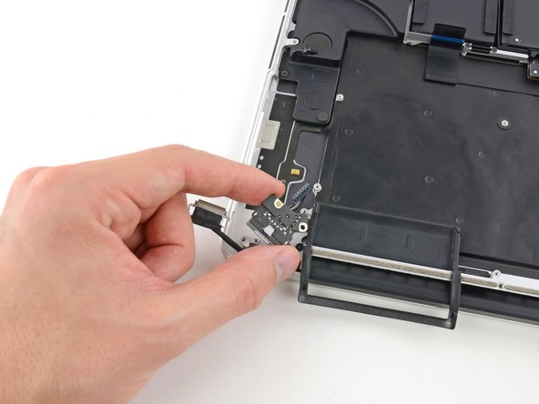
MacBook Pro에서 I/O 보드 케이블을 분리하세요.
-
-
-
-
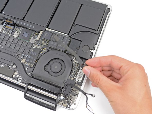
스퍼저의 끝을 사용하여 I/O 보드 데이터 케이블 잠금 장치를 뒤집어 컴퓨터의 배터리 쪽을 향해 돌리세요.
-
스퍼저의 납작한 끝을 사용하여 I/O 보드 데이터 케이블을 로직 보드의 소켓에서 똑바로 밀어내세요.
-
-
-
스퍼저의 납작한 끝을 사용하여 왼쪽 스피커 커넥터를 들어 올려 로직 보드의 소켓에서 빼내세요.
-
스퍼저의 끝을 사용하여 오른쪽 스피커 커넥터를 로직 보드의 소켓에서 위로 들어 올려 빼내세요.
-
-
이 단계는 번역되지 않았습니다. 번역을 도와주십시오
-
Remove the two 2.5 mm T5 Torx screws securing the MagSafe DC-In board to the upper case.
-
Slide the MagSafe DC-In board towards the right to free it from its recess within the upper case.
-
Lift and remove the MagSafe DC-In board out of the upper case assembly.
-


다른 21명이 해당 안내서를 완성하였습니다.

댓글 11개
I have a 820-3332 logic board (late 2013 MBP 15" Retina, same as this how-to) ) that is missing the socket on the underside of the logic board the magsafe board's wired connection slides into on the underside of the logic board as shown in the final steps. I can't find any mention of a new one anywhere. Looks like it was glued on at the factory. So I'm sitting here with a brand new magsafe 2 board with no way to attach it to the logic board. I though of soldering it directly to the pins that the socket mounts up against on the logic board but there are six pins on the logic board and five wires going to five connection points inside the connector that slides into the socket on the board. Looking at the six pin holes in the new magsafe 2 board connector from the top I see three wires, an empty pin hole and then two wires so I wouldn't even know which pins to attach to which board.
Anyone have any suggestions for this mess?
Any suggestions?
Wow! Somewhat complicated to get that DC board out. Wondering if I should even attempt this.
I have a liquid-damaged (coffee) MBP of this vintage. If I plug in the power adapter, the machine boots and runs fine; however, it shows the battery is "not available" in the battery menu and, when I unplug the magsafe adapter, the machine immediately powers off. As the logic board seems to work fine when plugged in, what do you think about attempting to stick in a DC board? Or is that battery "not available" message an indicator that the battery is also hosed? I don't see any obvious damage to the battery (but...).
Thanks for any advice.
This guide is very good and simple to follow. It may seem tricky but it really isn’t, just take your time to unscrew everything and place them in labeled bins, so you can remember where each screw goes.
I had a bit of trouble with the logic board, after everything was unscrewed it took some fiddling around to finally get the logic board to release and lift up.
Great tutorial.
Great, thank you. I got a 20 euro MagSafe board and it works perfectly.
The guide is accurate, and it is indeed easier than I expected.
For reassembly though I had to take out the logic board twice again because one of the small connectors ‘stayed behind’ the logic board and I only discovered later.
So a tip is to count the connectors you removed, and count again to make sure all are in place to connect and didn't stay in an unreachable place before you reattach the logic board.
Also as another tip, for easier reassembly, I put all the screws (and some parts) on the adhesive tape so they stayed in place and I could spatially fix them. I glued the tape to a paper sheet so I could take notes at which step the screws belonged and also other notes.