이 버전에는 잘못된 편집 사항이 있을 수 있습니다. 최신 확인된 스냅샷으로 전환하십시오.
필요한 것
-
-
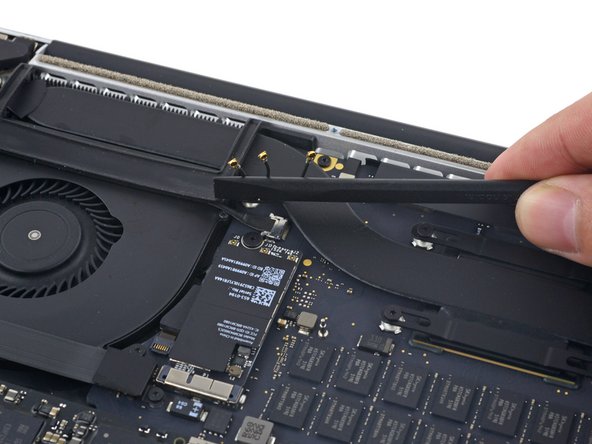
스퍼저 또는 핀셋을 사용하여 AirPort 안테나 케이블 세 개를 AirPort 보드의 소켓에서 똑바로 들어 올려 구부려서 방해가 되지 않도록 하세요.
-
-
이 단계는 번역되지 않았습니다. 번역을 도와주십시오
-
Remove the four 2.2 mm T5 Torx screws securing the I/O board cable connector covers.
-
-
이 단계는 번역되지 않았습니다. 번역을 도와주십시오
-
Remove the left connector cover.
-
Use the flat end of a spudger to pry the left end of the I/O board cable up from its socket on the logic board.
-
-
이 단계는 번역되지 않았습니다. 번역을 도와주십시오
-
Remove the right connector cover.
-
Use the flat end of a spudger to pry the right end of the I/O board cable up from its socket on the logic board.
-
-
이 단계는 번역되지 않았습니다. 번역을 도와주십시오
-
Peel the I/O board cable up from the adhesive securing it to the fan.
-
Remove the cable.
-
-
이 단계는 번역되지 않았습니다. 번역을 도와주십시오
-
Use a T5 Torx driver to remove the following three screws securing the right fan to the logic board:
-
One 5.0 mm screw with a 2.0 mm long shoulder
-
One 4.0 mm screw with a wide head
-
One 4.4 mm screw
-
-
-
이 단계는 번역되지 않았습니다. 번역을 도와주십시오
-
Use the tip of a spudger to flip up the retaining flap on the right fan ribbon cable ZIF socket.
-
-
이 단계는 번역되지 않았습니다. 번역을 도와주십시오
-
Lift the fan and push it gently towards the back edge of the MacBook to free the fan cable from its socket.
-
Remove the fan.
-
-
이 단계는 번역되지 않았습니다. 번역을 도와주십시오
-
Remove the following three screws securing the left fan to the logic board:
-
One 3.6 mm T5 Torx screw with a wide head
-
One 5.0 mm T5 Torx screw with a 2.0 mm long shoulder
-
One 4.4 mm T5 Torx screw
-
-
이 단계는 번역되지 않았습니다. 번역을 도와주십시오
-
Use the tip of a spudger to flip up the retaining flap on the left fan ribbon cable ZIF socket.
-
-
이 단계는 번역되지 않았습니다. 번역을 도와주십시오
-
Lift the fan and push it gently towards the back edge of the MacBook to free the fan cable from its socket.
-
Remove the fan.
-
-
이 단계는 번역되지 않았습니다. 번역을 도와주십시오
-
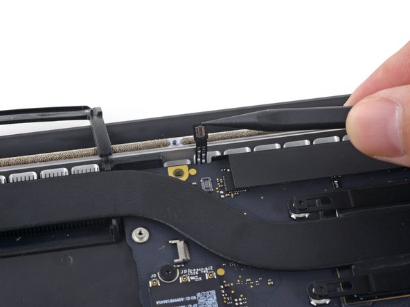
Remove the single 2.9 mm T5 Torx screw securing the SSD to the logic board.
-
-
이 단계는 번역되지 않았습니다. 번역을 도와주십시오
-
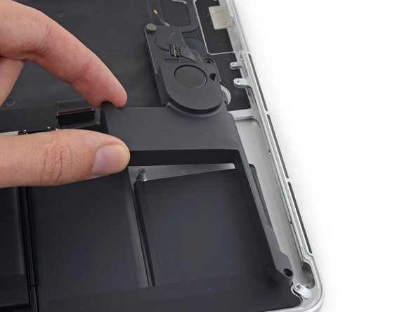
Lift the end of the SSD up enough to pass over the speaker directly behind it.
-
Pull the SSD straight out of its socket on the logic board.
-
-
이 단계는 번역되지 않았습니다. 번역을 도와주십시오
-
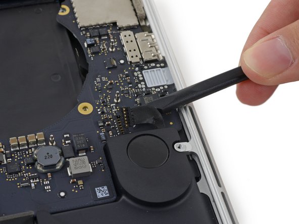
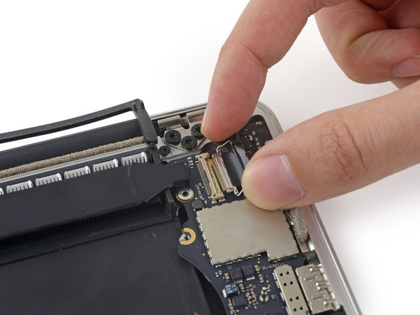
Use the point of a spudger to flip up the locking mechanism on the I/O board connector.
-
Flip the spudger around and use the flat end to slide the I/O cable out of the connector.
-
-
이 단계는 번역되지 않았습니다. 번역을 도와주십시오
-
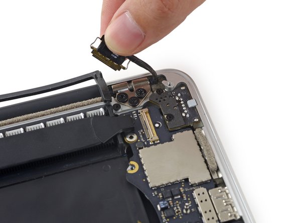
Slightly lift the interior edge of the I/O board and pull it toward the center of the MacBook, away from the side of the case.
-
Remove the I/O board.
-
-
이 단계는 번역되지 않았습니다. 번역을 도와주십시오
-
Remove the two 2.2 mm Torx T5 screws securing the touchpad cable connector cover to the logic board.
-
Remove the cover.
-
-
이 단계는 번역되지 않았습니다. 번역을 도와주십시오
-
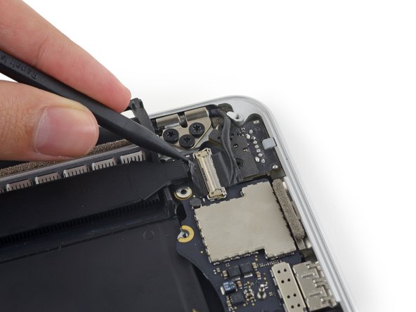
Use the flat end of a spudger to disconnect the touchpad cable connector from its socket in the logic board.
-
-
이 단계는 번역되지 않았습니다. 번역을 도와주십시오
-
Remove the following six screws securing the logic board assembly to the upper case.
-
One 3.8 mm T5 Torx screw
-
Two 5.7 mm T5 Torx screws
-
One 5.6 mm T5 Torx screw (this one is silver and has a taller head than the others)
-
One 2.6 mm T5 Torx screw
-
One 3.2 mm T5 Torx screw
-
-
이 단계는 번역되지 않았습니다. 번역을 도와주십시오
-
The following steps will detail disconnecting these six connectors. Be sure to read each step, as these connectors come in different styles that disconnect differently.
-
Microphone cable
-
Left speaker cable
-
Keyboard data cable
-
Right speaker cable
-
Keyboard backlight cable
-
Display data cable
-
-
이 단계는 번역되지 않았습니다. 번역을 도와주십시오
-
Use the tip of a spudger to flip up the retaining flap on the microphone ribbon cable ZIF socket.
-
Pull the microphone ribbon cable out of its socket, parallel to the logic board.
-
-
이 단계는 번역되지 않았습니다. 번역을 도와주십시오
-
Use the flat end of a spudger to pry the left speaker connector up and out of its socket on the logic board.
-
Gently fold the cable up and out of the way of the logic board.
-
-
이 단계는 번역되지 않았습니다. 번역을 도와주십시오
-
Peel back the tape covering the top of the keyboard data cable connector.
-
-
이 단계는 번역되지 않았습니다. 번역을 도와주십시오
-
Use the tip of a spudger to flip up the retaining flap on the keyboard data cable ZIF socket.
-
Pull the keyboard data cable out of its ZIF socket. Be sure to pull parallel to the logic board, and not straight up.
-
-
이 단계는 번역되지 않았습니다. 번역을 도와주십시오
-
Use the tip of a spudger to pry the right speaker connector up and out of its socket on the logic board.
-
Gently fold the cable up and out of the way of the logic board.
-
-
이 단계는 번역되지 않았습니다. 번역을 도와주십시오
-
Use the point of a spudger to pry the keyboard backlight connector up from its socket on the logic board.
-
-
이 단계는 번역되지 않았습니다. 번역을 도와주십시오
-
Use the tip of a spudger to flip up the display data cable lock and rotate it toward the MagSafe 2 power port side of the computer.
-
-
이 단계는 번역되지 않았습니다. 번역을 도와주십시오
-
Pull the display data cable straight out of its socket on the logic board.
-
Gently bend the display data cable toward the display hinge, to expose the screws on the MagSafe 2 board.
-
-
이 단계는 번역되지 않았습니다. 번역을 도와주십시오
-
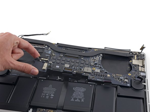
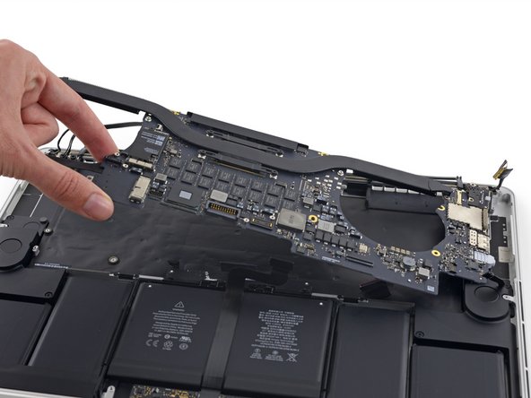
Lift and pull the entire logic board assembly away from the wall of the upper case.
-
-
이 단계는 번역되지 않았습니다. 번역을 도와주십시오
-
Remove the following screws securing the left speaker to the upper case:
-
2.7 mm T5 Torx screw
-
6.9 mm T5 Torx screw (with 4.5 mm shoulder)
-
5.6 mm T5 Torx screw
-
-
이 단계는 번역되지 않았습니다. 번역을 도와주십시오
-
Remove the left speaker by pulling it slightly away from the side of the upper case, and out from under the aluminum tab blocking it in.
-


다른 73명이 해당 안내서를 완성하였습니다.

댓글 17개
Hi! Such an excellent guide you’ve made. But I wonder, if I want to replace only the speaker, should I disassemble most of the parts or just doing step 41-42? Because I’m too afraid that I’ll break those small wirings and connectors.. while my only problem is the speaker.
Unfortunately, you must disassemble the whole machine - the board is covering a portion of the speaker and therefore it is impossible to remove with the board still on there.
Hi, I just went through replacing the left speaker and the screen. So much more involved to get to the left speaker than changing the screen.
But the replacement speaker is only giving me highs and not bass. Anyone ran into this issue? could it be a faulty speaker? I bought it here on ifixit. I don’t suppose it is from a bad replacement procedure that I could have done. Either the speaker has sound or it doesn’t?
Thanks.
No, have not noticed a decrease in bass from the replacement speaker. (bought used from eBay) Not that you’d want to disassemble everything again but there does seem to be an air intake opening near the end of the long section of the speaker. Perhaps it’s clogged? Also, the shape of the inner speaker is different on the replacement - original is round and the replacement is hexagon, though they both seem to sound the same.
Same. Replaced 2 speakers— one was low sounding, neither any bass. Returned, replaced again, same issue. At wits end.