이 버전에는 잘못된 편집 사항이 있을 수 있습니다. 최신 확인된 스냅샷으로 전환하십시오.
필요한 것
-
-
Mac 전원을 켜고 Terminal/터미널을 시작하세요.
-
다음 명령을 복사하여 Terminal/터미널에 붙여 넣으세요 (또는 정확히 입력하세요).
-
sudo nvram AutoBoot=%00
-
[return]을 누르세요. 관리자 암호 입력 메시지가 나타나면 관리자 암호를 입력하고 [return]을 다시 누르세요. 참고: return 키는 ⏎ 또는 "enter/입력"으로 표시되어 있을 수도 있습니다.
-
sudo nvram AutoBoot=%03
-
-
이 단계는 번역되지 않았습니다. 번역을 도와주십시오
-
Use a P5 Pentalobe driver to remove six screws securing the lower case, of the following lengths:
-
Four 4.7 mm screws
-
Two 6.6 mm screws
-
-
이 단계는 번역되지 않았습니다. 번역을 도와주십시오
-
Press a suction handle into place near the front edge of the lower case, between the screw holes.
-
Pull up on the suction handle just enough to open a small gap under the lower case.
-
-
이 단계는 번역되지 않았습니다. 번역을 도와주십시오
-
Slide the corner of an opening pick into the gap you just created underneath the lower case.
-
Slide the opening pick around the nearest corner and then halfway up the side of the MacBook Pro.
-
-
이 단계는 번역되지 않았습니다. 번역을 도와주십시오
-
Repeat the previous step on the other side, using an opening pick to to release the second clip.
-
-
이 단계는 번역되지 않았습니다. 번역을 도와주십시오
-
Lift the front edge of the lower case (the side opposite the display hinge) enough to slide your fingertips underneath and get a good grip on it.
-
-
이 단계는 번역되지 않았습니다. 번역을 도와주십시오
-
Pull firmly to slide the lower case towards the front edge of the MacBook (away from the hinge area) to separate the last of the clips securing the lower case.
-
Pull first at one corner, then the other.
-
-
이 단계는 번역되지 않았습니다. 번역을 도와주십시오
-
Remove the lower case.
-
Set it in place and align the sliding clips near the display hinge. Press down and slide the cover toward the hinge. It should stop sliding as the clips engage.
-
When the sliding clips are fully engaged and the lower case looks correctly aligned, press down firmly on the lower case to engage the four hidden clips underneath. You should feel and hear them snap into place.
-
-
이 단계는 번역되지 않았습니다. 번역을 도와주십시오
-
Peel up and remove the insulating sticker covering the battery board, on the edge of the logic board nearest the battery.
-
If the cover doesn't peel up easily, apply mild heat with an iOpener, hair dryer, or heat gun to soften the adhesive underneath, and try again.
-
-
이 단계는 번역되지 않았습니다. 번역을 도와주십시오
-
Peel back any tape covering the battery board data cable connector.
-
Use a spudger to gently pry up the locking flap on the ZIF connector for the battery board data cable.
-
-
이 단계는 번역되지 않았습니다. 번역을 도와주십시오
-
Disconnect the battery board data cable by sliding it out from its socket on the logic board.
-
Slide parallel to the logic board, in the direction of the cable.
-
-
이 단계는 번역되지 않았습니다. 번역을 도와주십시오
-
Pry up and disconnect the locking flap on the connector at the opposite end of the battery board data cable.
-
-
이 단계는 번역되지 않았습니다. 번역을 도와주십시오
-
Slide the battery board data cable out of its socket on the battery board, and remove it completely.
-
-
이 단계는 번역되지 않았습니다. 번역을 도와주십시오
-
Use a T5 Torx driver to remove the 3.7 mm pancake screw securing the battery power connector.
-
-
이 단계는 번역되지 않았습니다. 번역을 도와주십시오
-
Use a spudger to lift the battery power connector, disconnecting the battery.
-
-
이 단계는 번역되지 않았습니다. 번역을 도와주십시오
-
Use a T3 Torx driver to remove the two 1.9 mm screws securing the cover bracket for the keyboard and trackpad cable connectors.
-
Remove the bracket.
-
-
이 단계는 번역되지 않았습니다. 번역을 도와주십시오
-
Use a spudger to disconnect the trackpad cable by prying its connector straight up from the logic board.
-
-
-
이 단계는 번역되지 않았습니다. 번역을 도와주십시오
-
Apply mild heat to the trackpad ribbon cable to soften the adhesive securing it to the battery.
-
-
이 단계는 번역되지 않았습니다. 번역을 도와주십시오
-
Carefully peel the trackpad cable up off the battery, and push it out of the way.
-
-
이 단계는 번역되지 않았습니다. 번역을 도와주십시오
-
Use a T5 Torx driver to remove the 13 screws securing the trackpad assembly:
-
Nine 5.8 mm screws
-
Four 4.9 mm screws
-
-
이 단계는 번역되지 않았습니다. 번역을 도와주십시오
-
Swing the display open slightly, but keep the MacBook upside-down. The trackpad assembly should separate and lay flat on the display.
-
Carefully feed the trackpad's ribbon cable through its slot in the chassis.
-
-
이 단계는 번역되지 않았습니다. 번역을 도와주십시오
-
As you remove the trackpad assembly, be very careful not to lose the nine small metal washers resting on the screw posts. (They will fly off and get lost with very little provocation.)
-
Remove the trackpad assembly.
-
-
이 단계는 번역되지 않았습니다. 번역을 도와주십시오
-
Use your spudger to disconnect the keyboard by prying its connector straight up from the logic board.
-
-
이 단계는 번역되지 않았습니다. 번역을 도와주십시오
-
Use a T3 Torx driver to remove the two 3.5 mm screws securing the cover on the display board flex cable.
-
Remove the display board flex cover.
-
-
이 단계는 번역되지 않았습니다. 번역을 도와주십시오
-
Using a T3 Torx driver, remove the two 1.7 mm screws securing the bracket for the display board cable connector.
-
Remove the display board cable connector bracket.
-
-
이 단계는 번역되지 않았습니다. 번역을 도와주십시오
-
Pry the display board flex cable straight up from its socket to disconnect it from the display board.
-
-
이 단계는 번역되지 않았습니다. 번역을 도와주십시오
-
Use a T3 Torx driver to remove the four 2.0 mm screws from the hinge covers (two screws on each side).
-
-
이 단계는 번역되지 않았습니다. 번역을 도와주십시오
-
Use a T3 Torx driver to remove the two 2.4 mm screws securing the cover bracket for the Touch ID and headphone jack cable connectors.
-
Remove the bracket.
-
-
이 단계는 번역되지 않았습니다. 번역을 도와주십시오
-
Disconnect the headphone jack flex connector by prying it straight up from the logic board.
-
-
이 단계는 번역되지 않았습니다. 번역을 도와주십시오
-
Disconnect the power button and Touch ID sensor by prying its connector straight up from the logic board.
-
-
이 단계는 번역되지 않았습니다. 번역을 도와주십시오
-
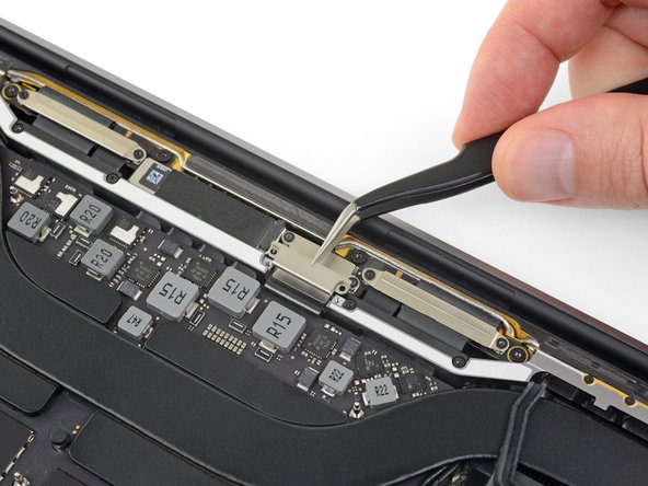
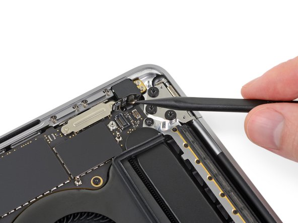
Using a T3 Torx driver, remove the 1.3 mm screw securing the cover bracket for the Touch Bar digitizer connector.
-
-
이 단계는 번역되지 않았습니다. 번역을 도와주십시오
-
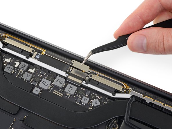
Using your tweezers, slide the bracket toward the side edge of the MacBook Pro until it clears the slotted retaining tab on the logic board.
-
Remove the bracket.
-
-
이 단계는 번역되지 않았습니다. 번역을 도와주십시오
-
Disconnect the Touch Bar digitizer cable by prying it straight up from the logic board.
-
-
이 단계는 번역되지 않았습니다. 번역을 도와주십시오
-
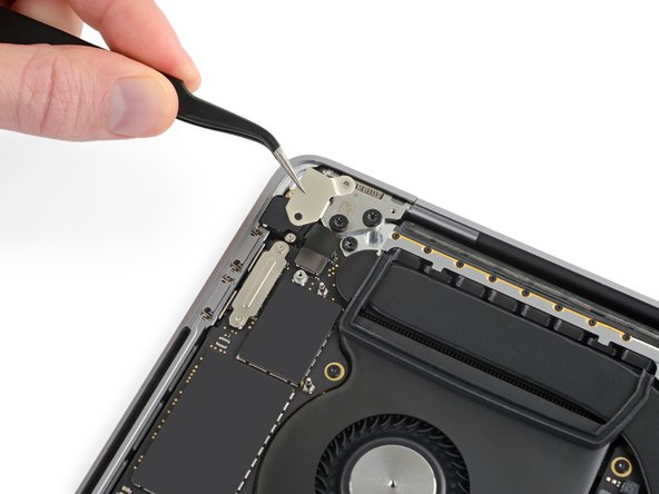
Use a T3 Torx driver to remove the two 1.9 mm screws securing the bracket for the Touch Bar display cable connector.
-
Remove the bracket.
-
-
이 단계는 번역되지 않았습니다. 번역을 도와주십시오
-
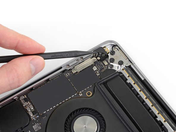
Disconnect the Touch Bar display cable by prying its connector straight up from the logic board.
-
-
이 단계는 번역되지 않았습니다. 번역을 도와주십시오
-
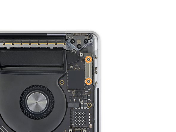
Using a T3 Torx Driver:
-
Remove the two 1.3 mm screws securing the Thunderbolt flex cable cover on the left.
-
Remove two more 1.3 mm screws from the Thunderbolt cable cover on the right.
-
-
이 단계는 번역되지 않았습니다. 번역을 도와주십시오
-
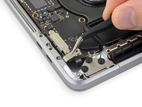
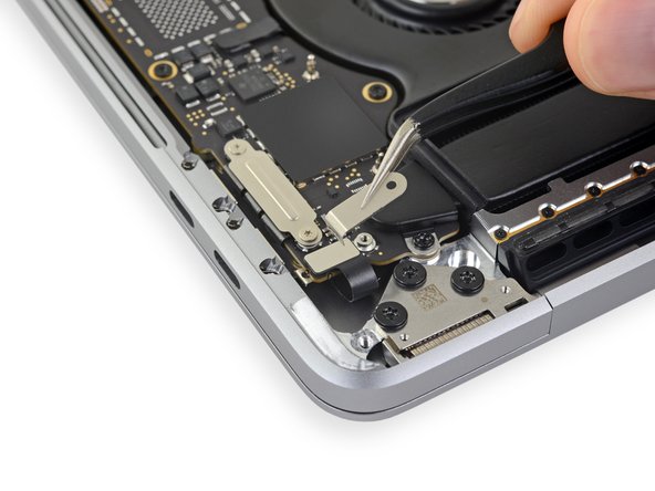
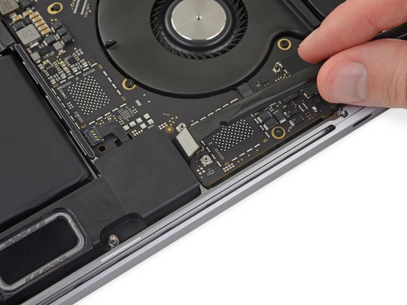
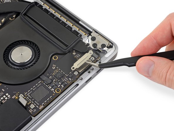
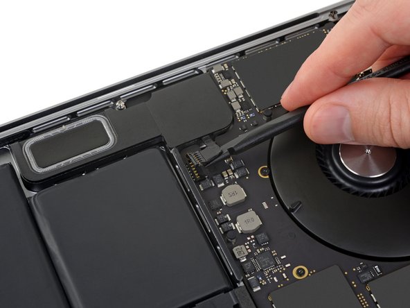
Use a spudger to disconnect the left-side Thunderbolt flex cable by prying it straight up from the logic board.
-
Pry from the inside edge, nearest the fan.
-
Gently push the flex cable connector off to the side so it doesn't interfere with logic board removal.
-
-
이 단계는 번역되지 않았습니다. 번역을 도와주십시오
-
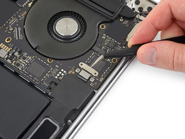
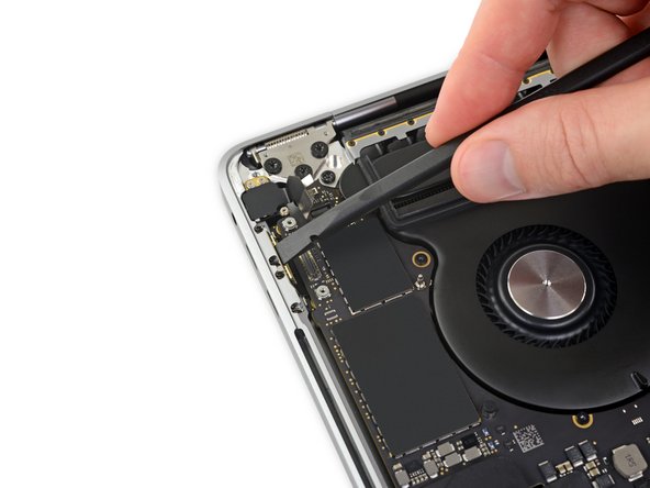
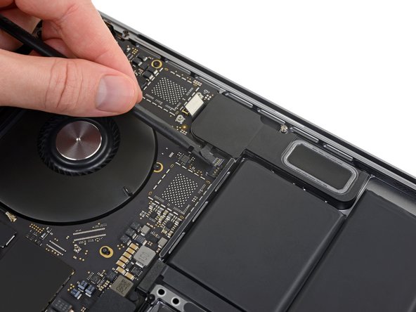
Repeat to disconnect the Thunderbolt flex cable connector on the opposite side.
-
Carefully push the flex cable connector aside so there's clearance for the logic board to come out without snagging.
-
-
이 단계는 번역되지 않았습니다. 번역을 도와주십시오
-
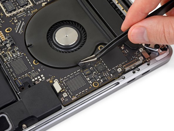
Disconnect the two speaker connectors by sliding the flat end of your spudger underneath each cable near its connector.
-
Gently twist or pry up to disconnect both speakers.
-
-
이 단계는 번역되지 않았습니다. 번역을 도와주십시오
-
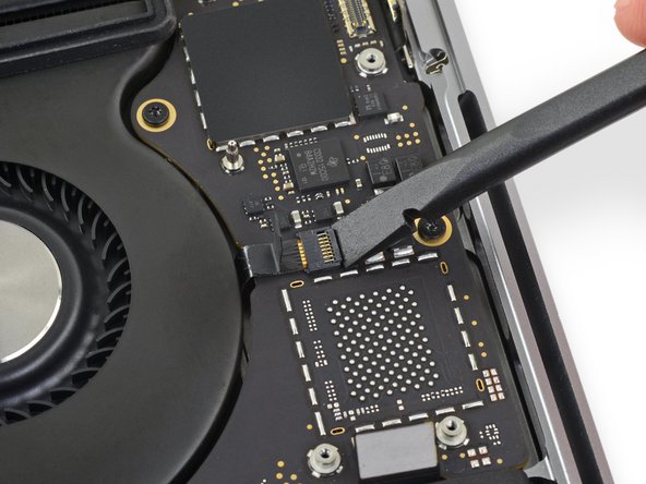
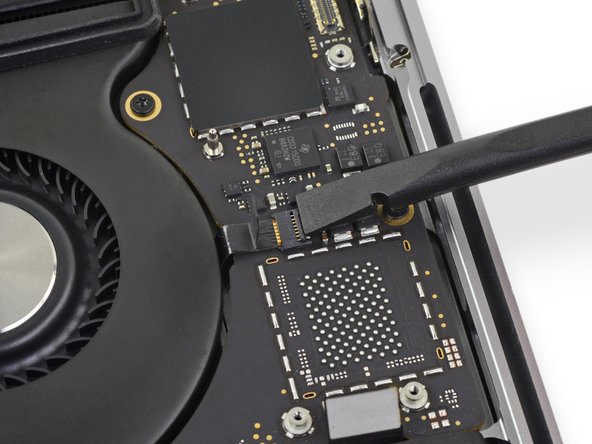
Open the locking flap on the microphone cable's ZIF connector by prying it straight up from the logic board.
-
-
이 단계는 번역되지 않았습니다. 번역을 도와주십시오
-
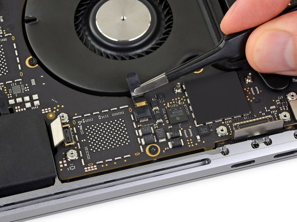
Disconnect the microphone by pulling its cable toward the fan until it releases from its socket.
-
If possible, pull on the tape attached to the cable, rather than the cable itself, to reduce the risk of damage.
-
-
이 단계는 번역되지 않았습니다. 번역을 도와주십시오
-
Use a T5 Torx driver to remove the single 2.9 mm screw securing the antenna cable bundle.
-
-
이 단계는 번역되지 않았습니다. 번역을 도와주십시오
-
Disconnect all three antenna cables by prying each one straight up from its socket.
-
Slide your tweezers or the flat end of your spudger underneath each cable until it's near the socket, and then gently twist or pry up to disconnect it.
-
-
이 단계는 번역되지 않았습니다. 번역을 도와주십시오
-
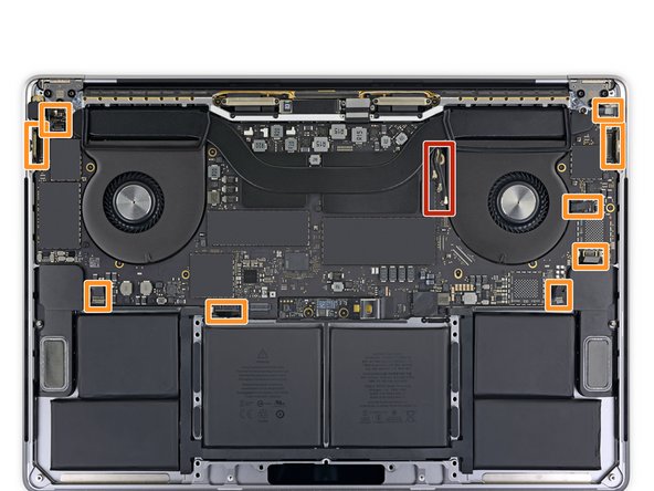
Remove all ten screws securing the logic board assembly:
-
Two 2.6 mm T3 Torx screws
-
Five 2.9 mm T5 Torx screws
-
One 3.7 mm T5 Torx screw
-
One 3.9 mm T8 Torx screw (large head)
-
One 4.0 mm T8 Torx screw
-
-
이 단계는 번역되지 않았습니다. 번역을 도와주십시오
-
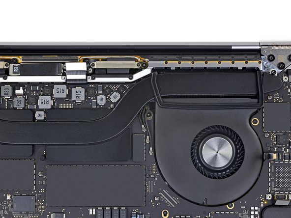
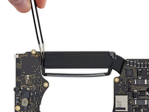
Peel up (but don't remove) the two rubber vibration damping strips from the adhesive holding them to the fans.
-
If needed, apply mild heat with an iOpener, hair dryer, or heat gun to soften the adhesive and make the dampers easier to separate.
-
-
이 단계는 번역되지 않았습니다. 번역을 도와주십시오
-
Check the alignment of the rubber vibration dampers, and adjust them as needed.
-
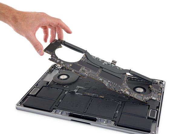
Feed the antenna cable bundle through the gap between the logic board and heat sink, and make sure it lines up correctly as you lower the board into place.
-
Verify that no cables get trapped under the board as you install it. Check each marked location carefully.
-


다른 한 분이 해당 안내서를 완성하였습니다.

