이 버전에는 잘못된 편집 사항이 있을 수 있습니다. 최신 확인된 스냅샷으로 전환하십시오.
필요한 것
-
-
하단 케이스를 상단 케이스에 고정하는 다음 나사 열 개를 풀어주세요:
-
13.5mm (14.1mm) Phillips/십자 나사 세 개.
-
3mm Phillips/십자 나사 일곱 개
-
-
-
부착된 플라스틱 당김 탭을 사용하여 배터리를 상단 케이스에서 분리하세요.
-
배터리를 100% 충전한 다음 최소 두 시간 더 충전하세요. 그런 다음 플러그는 뽑고 정상적으로 사용하여 배터리를 방전하세요. 배터리 부족 경고가 나타나면 작업을 저장하고 배터리 부족으로 인해 절전 모드가 활성화될 때까지 노트북을 켜놓으세요. 최소한 5시간 이상을 기다리고 나서 노트북을 중단없이 100% 충전하세요.
-
새 배터리를 설치한 다음 비정상적 작동 또는 문제가 발생하면 MacBook의 SMC를 재설정해야 합니다.
-
-
이 단계는 번역되지 않았습니다. 번역을 도와주십시오
-
Remove the three 3.4 mm T6 Torx screws securing the left fan to the logic board.
-
-
이 단계는 번역되지 않았습니다. 번역을 도와주십시오
-
Use the flat end of a spudger to disconnect the left fan connector from the logic board.
-
-
이 단계는 번역되지 않았습니다. 번역을 도와주십시오
-
Use the flat end of a spudger to lift the right fan connector out of its socket on the logic board.
-
-
-
이 단계는 번역되지 않았습니다. 번역을 도와주십시오
-
Remove the three 3.4 mm (3.1 mm) T6 Torx screws securing the right fan to the logic board.
-
Lift the right fan out of its opening in the logic board.
-
-
이 단계는 번역되지 않았습니다. 번역을 도와주십시오
-
Use the flat end of a spudger to pry the AirPort/Bluetooth connector up from its socket on the logic board.
-
-
이 단계는 번역되지 않았습니다. 번역을 도와주십시오
-
Use the flat end of a spudger to lift the optical drive connector out of its socket on the logic board.
-
-
이 단계는 번역되지 않았습니다. 번역을 도와주십시오
-
Disconnect the hard drive/IR sensor cable from its socket on the logic board by lifting up from beneath its connector.
-
-
이 단계는 번역되지 않았습니다. 번역을 도와주십시오
-
Use the flat end of a spudger to lift the subwoofer/right speaker connector out of its socket on the logic board.
-
-
이 단계는 번역되지 않았습니다. 번역을 도와주십시오
-
Remove the two 1.5 mm ( 1.2 mm ) Phillips screws securing the keyboard/trackpad cable cover to the logic board.
-
Lift the cover off the logic board and set it aside.
-
-
이 단계는 번역되지 않았습니다. 번역을 도와주십시오
-
Use the flat end of a spudger to pry the trackpad connector up and out of its socket on the logic board.
-
-
이 단계는 번역되지 않았습니다. 번역을 도와주십시오
-
Use your fingernail to flip up the retaining flap on the keyboard ribbon cable ZIF socket.
-
Use the tip of a spudger to pull the keyboard ribbon cable out of its socket.
-
-
이 단계는 번역되지 않았습니다. 번역을 도와주십시오
-
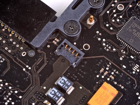
Use the flat end of a spudger to lift the battery indicator connector up and out of its socket on the logic board.
-
-
이 단계는 번역되지 않았습니다. 번역을 도와주십시오
-
Grab the plastic pull tab secured to the display data cable lock and rotate it toward the DC-In side of the computer.
-
Pull the display data cable straight out of its socket on the logic board.
-
-
이 단계는 번역되지 않았습니다. 번역을 도와주십시오
-
Use the tip of a spudger to flip up the retaining flap on the keyboard backlight ribbon cable ZIF socket.
-
Pull the keyboard backlight ribbon cable out of its socket.
-
-
이 단계는 번역되지 않았습니다. 번역을 도와주십시오
-
Remove the following nine screws:
-
Seven 3.4 mm ( 3.1 mm) T6 Torx screws on the logic board
-
Two 8 mm T6 Torx screws on the DC-In board
-
-
이 단계는 번역되지 않았습니다. 번역을 도와주십시오
-
Carefully lift the logic board assembly from its left side and work it out of the upper case, minding the optical drive cable and the I/O ports that may get caught during removal.
-
If necessary, use the flat end of a spudger to separate the microphone from the upper case.
-
Pull the I/O port side of the logic board away from the side of the upper case and remove the logic board assembly.
-
-
이 단계는 번역되지 않았습니다. 번역을 도와주십시오
-
Remove the six #1 Phillips screws securing the heat sink to the logic board.
-
-
이 단계는 번역되지 않았습니다. 번역을 도와주십시오
-
Remove the two 5 mm Phillips screws securing the left speaker to the logic board.
-
-
이 단계는 번역되지 않았습니다. 번역을 도와주십시오
-
Carefully pull the left speaker wires upward to lift the left speaker connector out of its socket on the logic board.
-
-
이 단계는 번역되지 않았습니다. 번역을 도와주십시오
-
Carefully pull the microphone cables upward to lift the microphone connector out of its socket on the logic board.
-
-
이 단계는 번역되지 않았습니다. 번역을 도와주십시오
-
Pull the DC-In board cables toward the heat sink to disconnect the DC-In board from its socket on the logic board.
-
-
이 단계는 번역되지 않았습니다. 번역을 도와주십시오
-
Release the tabs on each side of the RAM chip by simultaneously pushing each tab away from the RAM.
-
After the RAM chip has popped up, pull it straight out of its socket.
-
Logic board remains.
-
If you need to mount the heat sink back onto the logic board, we have a thermal paste guide that makes replacing the thermal compound easy.
-


다른 148명이 해당 안내서를 완성하였습니다.

댓글 30개
Can the CPU replaced on this Logic Board? Or I have to replace the whole Logic Board?!
Logic board completely
gzasuwa -
cpu is part of board
Hello. Why don't you remove RAM in the beginning? Thanks