이 버전에는 잘못된 편집 사항이 있을 수 있습니다. 최신 확인된 스냅샷으로 전환하십시오.
필요한 것
-
이 단계는 번역되지 않았습니다. 번역을 도와주십시오
-
With the case closed, place the Unibody top-side down on a flat surface.
-
Depress the grooved side of the access door release latch enough to grab the free end. Lift the release latch until it is vertical.
-
-
이 단계는 번역되지 않았습니다. 번역을 도와주십시오
-
The access door should now be raised enough to lift it up and out of the Unibody.
-
-
이 단계는 번역되지 않았습니다. 번역을 도와주십시오
-
Grab the translucent plastic tab and pull the battery up and out of the Unibody.
-
If the latch is depressed it will lock the battery in place.
-
-
이 단계는 번역되지 않았습니다. 번역을 도와주십시오
-
Remove the following eight screws securing the lower case to the chassis:
-
One 5.4 mm Phillips screw.
-
Three 14 mm Phillips screws.
-
Four 3.5 mm Phillips screws.
-
-
이 단계는 번역되지 않았습니다. 번역을 도와주십시오
-
Remove the following 5 screws securing the mid wall to the upper case:
-
Three 10.5 mm Phillips screws.
-
Two 3.7 mm Phillips screws.
-
-
이 단계는 번역되지 않았습니다. 번역을 도와주십시오
-
Remove the following six screws securing both the right fan and the left fan to the logic board:
-
Four 3.5 mm Phillips screws.
-
Two 3.2 mm Phillips screws.
-
-
이 단계는 번역되지 않았습니다. 번역을 도와주십시오
-
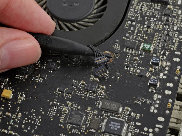
Use the tip of a spudger to lift the right fan connector straight up from its socket on the logic board.
-
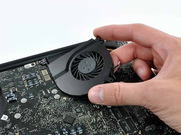
Remove the right fan from the case.
-
-
이 단계는 번역되지 않았습니다. 번역을 도와주십시오
-
Use the tip of a spudger to lift the left fan connector straight up from its socket on the logic board.
-
Remove the left fan from the case.
-
-
이 단계는 번역되지 않았습니다. 번역을 도와주십시오
-
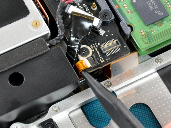
Remove any adhesive from the camera cable connector.
-
Disconnect the camera cable by pulling the male end out of its socket, parallel to the logic board, do not lift it upwards.
-
-
이 단계는 번역되지 않았습니다. 번역을 도와주십시오
-
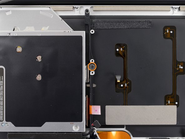
Use a spudger to carefully pry the optical drive connector straight up off its socket on the logic board.
-
-
-
이 단계는 번역되지 않았습니다. 번역을 도와주십시오
-
Using the flat end of a spudger, pry the subwoofer connector straight up off its socket on the logic board.
-
-
이 단계는 번역되지 않았습니다. 번역을 도와주십시오
-
Use the flat end of a spudger to pry the silver-colored hard drive cable connector straight up out of its socket on the logic board.
-
-
이 단계는 번역되지 않았습니다. 번역을 도와주십시오
-
Use a spudger to pry the trackpad connector straight up out of its socket on the logic board.
-
-
이 단계는 번역되지 않았습니다. 번역을 도와주십시오
-
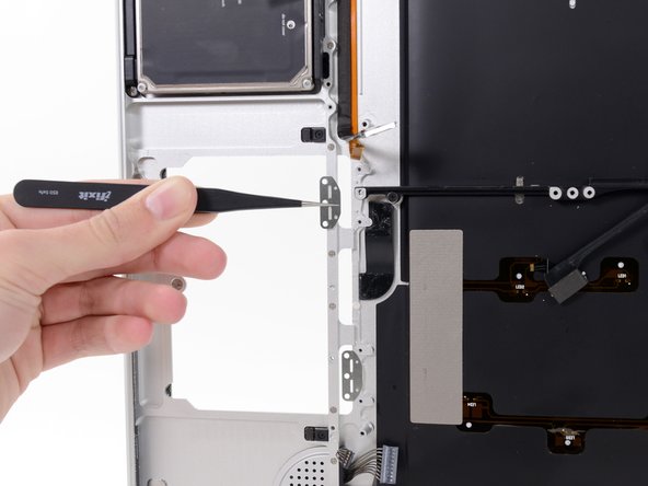
Using the tip of a spudger, flip up the IR/sleep LED ribbon cable retaining flap.
-
Pull the IR/sleep LED ribbon cable straight out of its socket.
-
-
이 단계는 번역되지 않았습니다. 번역을 도와주십시오
-
Use a spudger to pry the battery indicator light connector straight up out of its socket on the logic board.
-
-
이 단계는 번역되지 않았습니다. 번역을 도와주십시오
-
Using the tip of a spudger, flip up the keyboard ribbon cable retaining flap.
-
Pull the keyboard ribbon cable straight out of its socket.
-
-
이 단계는 번역되지 않았습니다. 번역을 도와주십시오
-
Using the tip of a spudger, flip up the express card cage ribbon cable retaining flap.
-
Pull the express card cage ribbon cable straight out of its socket.
-
-
이 단계는 번역되지 않았습니다. 번역을 도와주십시오
-
Using the flat end of a spudger, pry the microphone cable connector straight up out of its socket on the logic board.
-
-
이 단계는 번역되지 않았습니다. 번역을 도와주십시오
-
Grab the plastic pull tab secured to the display data cable lock and rotate it toward the DC-in side of the computer.
-
Pull the display data cable connector straight away from its socket.
-
-
이 단계는 번역되지 않았습니다. 번역을 도와주십시오
-
Locate the keyboard backlight ribbon cable (near the left fan space).
-
Using the tip of a spudger, flip up the keyboard backlight ribbon cable retaining flap.
-
Pull the keyboard backlight ribbon cable straight out of its socket.
-
-
이 단계는 번역되지 않았습니다. 번역을 도와주십시오
-
Remove seven 3.2 mm Phillips screws securing the logic board to the upper case.
-
-
이 단계는 번역되지 않았습니다. 번역을 도와주십시오
-
Remove two 7 mm Phillips screws securing the DC-in board to the upper case.
-
-
이 단계는 번역되지 않았습니다. 번역을 도와주십시오
-
Remove two 3.5 mm Phillips screws securing the bottom case clip to the upper case.
-
Lift the bottom case clip out of the upper case.
-
-
이 단계는 번역되지 않았습니다. 번역을 도와주십시오
-
Carefully lift the logic board assembly from the left side and work it out of the upper case, minding the port side that may get caught during removal.
-
-
이 단계는 번역되지 않았습니다. 번역을 도와주십시오
-
Lift the logic board enough to grab the battery connector and pull it straight away from its socket on the logic board.
-
Lift the logic board assembly out of the upper case.
-
-
이 단계는 번역되지 않았습니다. 번역을 도와주십시오
-
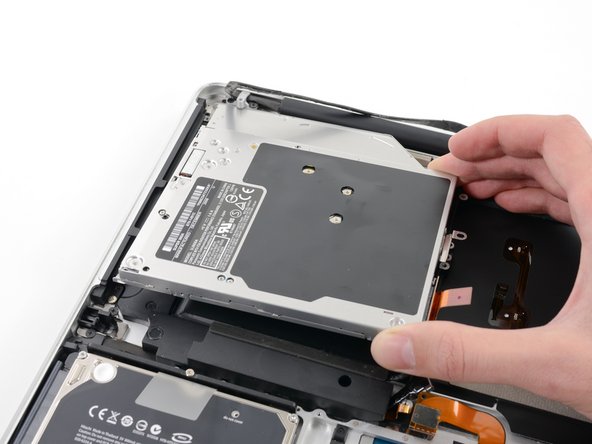
Remove the following three Phillips screws securing the optical drive to the upper case:
-
Two 2.5 mm Phillips screws.
-
One 3.5 mm Phillips screw.
-
Lift the optical drive out of the upper case.
-
-
이 단계는 번역되지 않았습니다. 번역을 도와주십시오
-
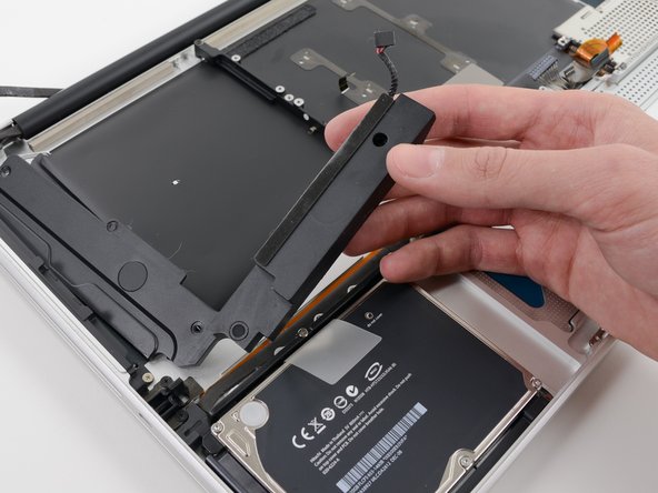
Remove the following four screws securing the subwoofer and right speaker to the upper case:
-
Two 3.2 mm Phillips screws.
-
One 2.6 mm Phillips screw.
-
One 5.0 mm Phillips screw.
-
Lift the subwoofer and right speaker assembly out of the upper case.
-
-
이 단계는 번역되지 않았습니다. 번역을 도와주십시오
-
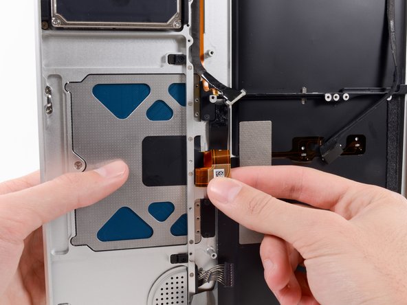
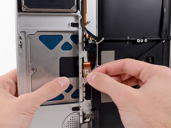
Insert the flat end of a spudger underneath the trackpad ribbon cable and gently peel it up from the adhesive securing it to the upper case.
-
-
이 단계는 번역되지 않았습니다. 번역을 도와주십시오
-
While holding the edge of the trackpad closest to the logic board with one hand, remove the six 1.3 mm Phillips screws securing the two brackets to the trackpad.
-
-
이 단계는 번역되지 않았습니다. 번역을 도와주십시오
-
While holding the trackpad in place with your left hand, fold the top of the trackpad ribbon cable down with your right hand so that it fits through its slot in the upper case.
-
Feed the ribbon cable through the slot as you push the portion of the trackpad closest to the keyboard out of the upper case.
-
-
이 단계는 번역되지 않았습니다. 번역을 도와주십시오
-
Remove the four 2.7 mm Phillips screws from the two trackpad bracket covers.
-


다른 55명이 해당 안내서를 완성하였습니다.

댓글 3개
What size is the tri-wing screwdriver needed to adjust the trackpad on this model?