이 버전에는 잘못된 편집 사항이 있을 수 있습니다. 최신 확인된 스냅샷으로 전환하십시오.
필요한 것
-
-
하단 케이스를 상단 케이스에 고정하는 다음 나사 열 개를 풀어주세요:
-
13.5mm (14.1mm) Phillips/십자 나사 세 개.
-
3mm Phillips/십자 나사 일곱 개
-
-
이 단계는 번역되지 않았습니다. 번역을 도와주십시오
-
Remove the following three screws securing the left fan to the logic board:
-
Two 3.5 mm T6 Torx screws.
-
One 4.2 mm T6 Torx screw.
-
-
이 단계는 번역되지 않았습니다. 번역을 도와주십시오
-
Use the flat end of a spudger to disconnect the left fan connector from the logic board.
-
-
이 단계는 번역되지 않았습니다. 번역을 도와주십시오
-
Use the flat end of a spudger to lift the right fan connector out of its socket on the logic board.
-
-
이 단계는 번역되지 않았습니다. 번역을 도와주십시오
-
Remove the three 3.4 mm (3.1 mm) T6 Torx screws securing the right fan to the logic board.
-
Lift the right fan out of its opening in the logic board.
-
-
이 단계는 번역되지 않았습니다. 번역을 도와주십시오
-
Use the flat end of a spudger to pry the AirPort/Bluetooth connector up from its socket on the logic board.
-
-
이 단계는 번역되지 않았습니다. 번역을 도와주십시오
-
Use the flat end of a spudger to lift the optical drive connector out of its socket on the logic board.
-
-
이 단계는 번역되지 않았습니다. 번역을 도와주십시오
-
Disconnect the hard drive/IR sensor cable from its socket on the logic board by lifting up from beneath its connector.
-
-
이 단계는 번역되지 않았습니다. 번역을 도와주십시오
-
Use the flat end of a spudger to lift the subwoofer/right speaker connector out of its socket on the logic board.
-
-
이 단계는 번역되지 않았습니다. 번역을 도와주십시오
-
Remove the two 1.5 mm ( 1.2 mm ) Phillips screws securing the keyboard/trackpad cable cover to the logic board.
-
Lift the cover off the logic board and set it aside.
-
-
이 단계는 번역되지 않았습니다. 번역을 도와주십시오
-
Use the flat end of a spudger to pry the trackpad connector up and out of its socket on the logic board.
-
-
-
이 단계는 번역되지 않았습니다. 번역을 도와주십시오
-
Use your fingernail to flip up the retaining flap on the keyboard ribbon cable ZIF socket.
-
Use the tip of a spudger to pull the keyboard ribbon cable out of its socket.
-
-
이 단계는 번역되지 않았습니다. 번역을 도와주십시오
-
Use the flat end of a spudger to lift the battery indicator connector up and out of its socket on the logic board.
-
-
이 단계는 번역되지 않았습니다. 번역을 도와주십시오
-
Grab the plastic pull tab secured to the display data cable lock and rotate it toward the DC-In side of the computer.
-
Pull the display data cable straight out of its socket on the logic board.
-
-
이 단계는 번역되지 않았습니다. 번역을 도와주십시오
-
Use the tip of a spudger to flip up the retaining flap on the keyboard backlight ribbon cable ZIF socket.
-
Pull the keyboard backlight ribbon cable out of its socket.
-
-
이 단계는 번역되지 않았습니다. 번역을 도와주십시오
-
Remove the following nine screws:
-
Seven 3.4 mm ( 3.1 mm) T6 Torx screws on the logic board
-
Two 8 mm T6 Torx screws on the DC-In board
-
-
이 단계는 번역되지 않았습니다. 번역을 도와주십시오
-
Carefully lift the logic board assembly from its left side and work it out of the upper case, minding the optical drive cable and the I/O ports that may get caught during removal.
-
If necessary, use the flat end of a spudger to separate the microphone from the upper case.
-
Pull the I/O port side of the logic board away from the side of the upper case and remove the logic board assembly.
-
-
이 단계는 번역되지 않았습니다. 번역을 도와주십시오
-
Remove the two 7.5 mm ( 7.2 mm )Tri-point screws securing the battery to the upper case.
-
-
이 단계는 번역되지 않았습니다. 번역을 도와주십시오
-
Carefully peel the battery warning label off the upper case between the battery and the optical drive to reveal an additional Tri-point screw.
-
Remove the last 7.5 mm ( 7.2 mm ) Tri-point screw securing the battery to the upper case.
-
-
이 단계는 번역되지 않았습니다. 번역을 도와주십시오
-
Use the attached plastic pull tab to remove the battery from the upper case.
-
-
이 단계는 번역되지 않았습니다. 번역을 도와주십시오
-
Remove the two Phillips screws securing the hard drive bracket to the upper case.
-
Remove the hard drive bracket from the upper case.
-
-
이 단계는 번역되지 않았습니다. 번역을 도와주십시오
-
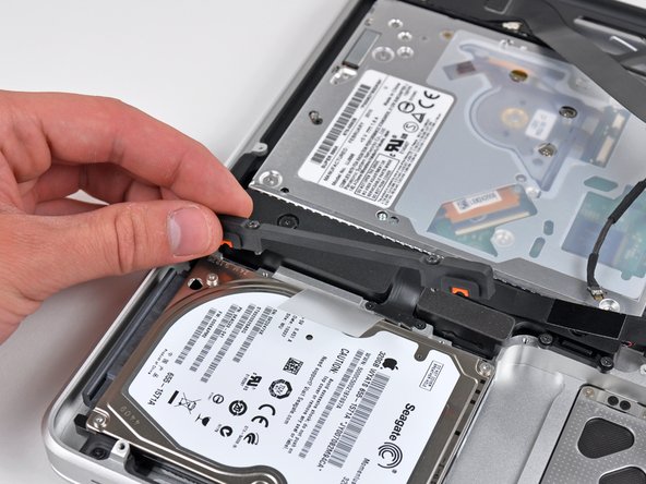
Using its attached pull tab, lift the hard drive out of the upper case.
-
-
이 단계는 번역되지 않았습니다. 번역을 도와주십시오
-
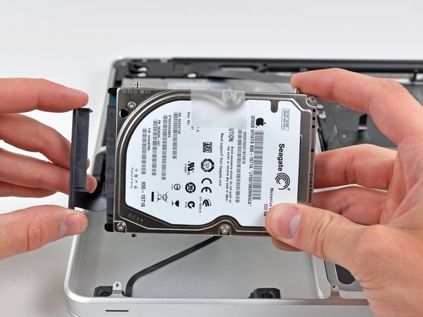
Pull the hard drive connector out of its socket on the hard drive.
-
Remove the hard drive and set it aside.
-
-
이 단계는 번역되지 않았습니다. 번역을 도와주십시오
-
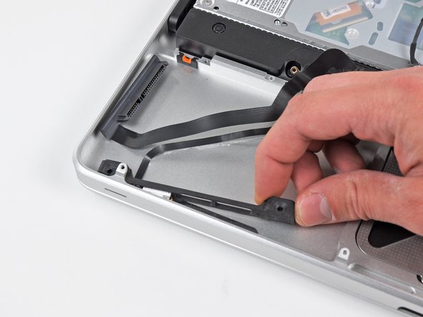
Remove the following four screws securing the hard drive/IR sensor cable to the upper case:
-
Two 2.5 mm ( 2.9 mm ) Phillips screws
-
Two 10 mm ( 9.6 mm ) Phillips screws
-
-
이 단계는 번역되지 않았습니다. 번역을 도와주십시오
-
Carefully peel the IR sensor cable off the adhesive securing it to the upper case.
-
Pull the hard drive bracket/IR sensor housing away from the side of the upper case.
-
Remove the hard drive/IR sensor cable from the upper case.
-
-
이 단계는 번역되지 않았습니다. 번역을 도와주십시오
-
Use the tip of a spudger to pry the four antenna connectors up from their sockets on the AirPort/Bluetooth board.
-
-
이 단계는 번역되지 않았습니다. 번역을 도와주십시오
-
De-route all four antenna cables from their channels in the AirPort/Bluetooth housing.
-
De-route the camera cable from its channel in the AirPort/Bluetooth housing.
-
-
이 단계는 번역되지 않았습니다. 번역을 도와주십시오
-
Remove the following two screws:
-
One 8.6 mm ( 8.4 mm ) Phillips screw
-
One 3.9 mm Phillips screw
-
Remove the AirPort/Bluetooth assembly from the upper case, minding any cables that may get caught.
-
-
이 단계는 번역되지 않았습니다. 번역을 도와주십시오
-
Remove the three 3.5 mm ( 3.3 mm ) T6 Torx screws securing the optical drive to the upper case.
-
Lift the optical drive near its connector and pull it away from the upper case to remove it from the computer.
-
-
이 단계는 번역되지 않았습니다. 번역을 도와주십시오
-
Remove the following six screws securing the subwoofer and right speaker to the upper case:
-
Two 3.2 mm ( 3.0 mm ) Phillips screws.
-
Two 12.3 mm Phillips screws.
-
One 2.5 mm Phillips screw.
-
One 8.3 mm ( 8.1 mm ) Phillips screw.
-
Lift the subwoofer and right speaker assembly out of the upper case.
-
-
이 단계는 번역되지 않았습니다. 번역을 도와주십시오
-
Remove the 8.6 mm Phillips screw securing the antenna/camera cable retainer to the top left portion of the upper case.
-
Remove the antenna/camera cable retainer from the upper case.
-
-
이 단계는 번역되지 않았습니다. 번역을 도와주십시오
-
Remove the 8.6 mm ( 7.0 mm ) Phillips screw securing the display data cable retainer to the top right portion of the upper case.
-
Remove the display data cable retainer from the upper case.
-
-
이 단계는 번역되지 않았습니다. 번역을 도와주십시오
-
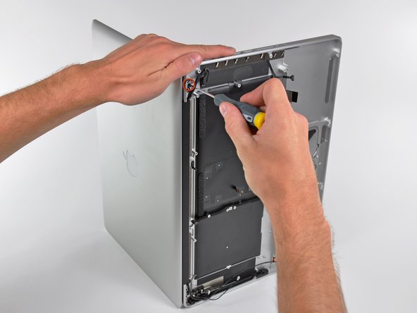
Remove two of the three 6 mm T6 Torx screws securing the right side of the display to the upper case.
-
-
이 단계는 번역되지 않았습니다. 번역을 도와주십시오
-
Remove two of the three 6 mm T6 Torx screws securing the left side of the display to the upper case.
-
-
이 단계는 번역되지 않았습니다. 번역을 도와주십시오
-
Open your MacBook Pro so the display is perpendicular to the upper case.
-
Place your opened MacBook Pro on a table as pictured.
-
While holding the display and upper case together with your left hand, remove the remaining T6 Torx screw from the upper display bracket.
-
-
이 단계는 번역되지 않았습니다. 번역을 도와주십시오
-
Remove the last remaining T6 Torx screw securing the display to the upper case.
-
-
이 단계는 번역되지 않았습니다. 번역을 도와주십시오
-
Grab the upper case with your right hand and rotate it slightly toward the top of the display so the upper display bracket clears the edge of the upper case.
-
Rotate the display slightly away from the upper case.
-
Lift the display up and away from the upper case, minding any brackets or cables that may get caught.
-
-
이 단계는 번역되지 않았습니다. 번역을 도와주십시오
-
If your replacement includes the battery level indicator, stop here.
-
Remove three 2.0 mm Phillips #00 screws securing the battery level indicator to the upper case.
-
-
이 단계는 번역되지 않았습니다. 번역을 도와주십시오
-
Use the tip of a spudger to gently pry up the edge of the metal shield covering the battery level indicator cable.
-


다른 33명이 해당 안내서를 완성하였습니다.

댓글 10개
If your doing this just to replace the keyboard. the keyboard can be replaced after this last step. I found one for $16 on ebay. the only challenge is removing the backlighting which is taped down and then unscrewing about 50 tiny screws to remove the keyboard. the above process takes about an hour and then another hour to just replace the keyboard.
Hi there, I replaced the keyboard on my MacBook pro 15'' mid 2012.
Now my computer turns on but shuts down after a few seconds, except if the charger is plugged in. Do you have any idea what I might have done wrong?
I already did the process 3 times 😥
Thanks,
Marta
marta p -
I completed this replacement successfully, with one glitch and two leftover items. The glitch: I failed to insert the keyboard ribbon cable at first. The leftover items: A multilayer soft pad, silvered, about 3x1 ¾-(7.5x4.5 cm) and a piece of foam in a quarter-round shape, 7/16”(1.2 cm) long, ⅛"(3-4mm) ,on a side, with a fine metal mesh on the long sides. I don’t recall in which step I removed either part. I’m hoping neither is critical, but I’ll replace either as best I can if I’m wrong. I have a photo of the two parts but I don’t see how to add it to the post.
Took me a little over 4 hours, but seems successful. Most of the middle row on my keyboard had stopped working, I was having to use an external. The new case works fine. The hardest part was definitely the logic board removal, but just be patient and methodical and use the spudger to loosen the adhesive that binds the microphone to the upper case. I also encountered two screws that stripped when unscrewing, and had to use some creativity to release those parts. 48 hours after replacement, everything is working, and the new keyboard is definitely an improvement. Time-consuming and stressful but so much cheaper than authorized repair.