주요 콘텐츠로 건너뛰기

MacBook Pro 17" Unibody Logic Board Replacement

단지 전제 조건
이 안내서는 다른 가이드의 선행 작업으로 사용하기 위한 것입니다. 그 자체로는 불완전합니다.

필요한 것

  1. MacBook Pro 17" Unibody Logic Board Replacement, Logic Board: 1 단계, 이미지 1/1
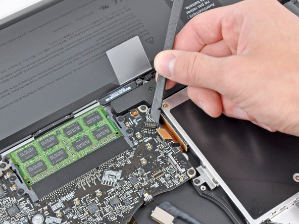
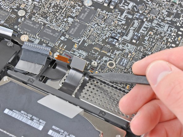
    • Use the flat end of a spudger to lift the left fan connector out of its socket on the logic board.

    • It is useful to twist the spudger axially from beneath the fan cable wires to release the connector.

  2. MacBook Pro 17" Unibody Logic Board Replacement: 2 단계, 이미지 1/2 MacBook Pro 17" Unibody Logic Board Replacement: 2 단계, 이미지 2/2
    • Remove the three 3.1 mm Phillips screws securing the left fan to the logic board.

    • Remove the left fan from the upper case, minding its cable that may get caught.

  3. MacBook Pro 17" Unibody Logic Board Replacement: 3 단계, 이미지 1/2 MacBook Pro 17" Unibody Logic Board Replacement: 3 단계, 이미지 2/2
    • Use the tip of a spudger or your fingernail to flip up the retaining flap on the keyboard backlight ribbon cable.

    • Be sure you are prying up on the retaining flap, not the socket itself.

    • Pull the keyboard backlight ribbon cable out of its socket.

  4. MacBook Pro 17" Unibody Logic Board Replacement: 4 단계, 이미지 1/1
    • Before disconnecting the camera cable, a small plastic retainer stuck to the logic board must first be moved out of the way.

    • Use the tip of a spudger to push the small plastic cable retainer away from the camera cable socket for enough clearance to remove the camera cable.

  5. MacBook Pro 17" Unibody Logic Board Replacement: 5 단계, 이미지 1/1
    • Pull the camera cable toward the optical drive opening to disconnect it from the logic board.

    • The camera cable socket is very fragile. Do not apply any upward force to this socket, as it may break off the logic board. Pull the camera cable parallel to the face of the logic board.

  6. MacBook Pro 17" Unibody Logic Board Replacement: 6 단계, 이미지 1/1
    • Use the flat end of a spudger to pry the optical drive connector up and out of its socket on the logic board.

  7. MacBook Pro 17" Unibody Logic Board Replacement: 7 단계, 이미지 1/1
    • Use the flat end of a spudger to lift the subwoofer & right speaker connector out of its socket on the logic board.

    • Pry up from beneath the wires.

  8. MacBook Pro 17" Unibody Logic Board Replacement: 8 단계, 이미지 1/2 MacBook Pro 17" Unibody Logic Board Replacement: 8 단계, 이미지 2/2
    • Use the tip of a spudger or your fingernail to flip up the retaining flap on the IR sensor ribbon cable socket.

    • Be sure you are prying up on the retaining flap, not the socket itself.

    • Pull the IR sensor ribbon cable out of its socket.

  9. MacBook Pro 17" Unibody Logic Board Replacement: 9 단계, 이미지 1/3 MacBook Pro 17" Unibody Logic Board Replacement: 9 단계, 이미지 2/3 MacBook Pro 17" Unibody Logic Board Replacement: 9 단계, 이미지 3/3
    • Remove the following four screws:

    • Two 3.5 mm Phillips screws

    • These may be T5 Torx screws in the Early 2011 model

    • Two 1.6 mm Phillips screws

    • Remove both connector shields from the logic board.

  10. MacBook Pro 17" Unibody Logic Board Replacement: 10 단계, 이미지 1/1
    • Use the flat end of a spudger to pry the trackpad connector up and out of its socket on the logic board.

  11. MacBook Pro 17" Unibody Logic Board Replacement: 11 단계, 이미지 1/2 MacBook Pro 17" Unibody Logic Board Replacement: 11 단계, 이미지 2/2
    • Use your fingernail to flip up the retaining flap on the keyboard ribbon cable socket.

    • Be sure you are prying up on the retaining flap, not the socket itself.

    • Pull the keyboard ribbon cable out of its socket.

    • For reassembly, it can be helpful to put a small piece of tape on the keyboard ribbon cable (being careful not to stick any to the contacts), to create a small handle. Align the cable with the socket and gently pull with the tape to fully seat it.

  12. MacBook Pro 17" Unibody Logic Board Replacement: 12 단계, 이미지 1/2 MacBook Pro 17" Unibody Logic Board Replacement: 12 단계, 이미지 2/2
    • Use your fingernail to flip up the retaining flap on the express card cage ribbon cable socket.

    • Be sure you are prying up on the retaining flap, not the socket itself.

    • Pull the express card cage ribbon cable out of its socket.

  13. MacBook Pro 17" Unibody Logic Board Replacement: 13 단계, 이미지 1/1
    • Use the flat end of a spudger to lift the hard drive cable connector up and out of its socket on the logic board.

  14. MacBook Pro 17" Unibody Logic Board Replacement: 14 단계, 이미지 1/2 MacBook Pro 17" Unibody Logic Board Replacement: 14 단계, 이미지 2/2
    • Use the tip of a spudger or your fingernail to flip up the retaining flap on the battery indicator cable socket.

    • Be sure you are prying up on the retaining flap, not the socket itself.

    • Pull the battery indicator ribbon cable out of its socket.

  15. MacBook Pro 17" Unibody Logic Board Replacement: 15 단계, 이미지 1/3 MacBook Pro 17" Unibody Logic Board Replacement: 15 단계, 이미지 2/3 MacBook Pro 17" Unibody Logic Board Replacement: 15 단계, 이미지 3/3
    • Lift the black plastic flap attached to the display data cable retainer and rotate it toward the DC-In side of the MacBook.

    • Pull the display data cable out of its socket.

    • The display data cable socket is very fragile. Do not lift the connector upward as you disconnect it, as the socket may break off the logic board. Pull the cable parallel to the face of the logic board.

  16. MacBook Pro 17" Unibody Logic Board Replacement: 16 단계, 이미지 1/1
    • Remove the following eight screws securing the logic board and DC-In board to the upper case:

    • Six 3.2 mm Phillips screws

    • These may be T6 Torx screws on the Early 2011 model.

    • Two 7.6 mm Phillips screws

  17. MacBook Pro 17" Unibody Logic Board Replacement: 17 단계, 이미지 1/2 MacBook Pro 17" Unibody Logic Board Replacement: 17 단계, 이미지 2/2
    • Handle the logic board assembly by its edges only.

    • Lift the logic board assembly from the side nearest the optical drive and lift it away from the upper case.

    • Note that you'll be removing the logic board and DC-in board together.

    • Carefully pull the ports and DC-In board away from the side of the upper case and remove the logic board assembly, minding any cables that may get caught.

결론

To reassemble your device, follow these instructions in reverse order.

Andrew Bookholt

586,109 평판

안내서 619개 작성하였습니다

댓글 0개

댓글 쓰기

조회 통계:

24 시간 전: 0

7일 전: 0

30일 전: 0

전체 시간: 1,435