주요 콘텐츠로 건너뛰기

이 버전에는 잘못된 편집 사항이 있을 수 있습니다. 최신 확인된 스냅샷으로 전환하십시오.

필요한 것

  1. , 하단 케이스: 1 단계, 이미지 1/1
    • 하단 케이스를 상단 케이스에 고정하는 다음 나사 열 개를 풀어주세요:

    • 13.5mm 십자 나사 세 개.

    • 3mm 십자 나사 일곱 개.

  2. : 2 단계, 이미지 1/2 : 2 단계, 이미지 2/2
    • 하단 케이스와 통풍구 사이에 손가락을 끼운 다음 위쪽으로 들어 올려 하단 케이스를 상단 케이스에 고정하고 있는 클립 두 개를 분리하세요.

    • 재조립할때는 하단 케이스를 조심히 정렬한 다음 두 클립이 모두 맞물릴 때까지 단단히 누르세요.

    • 하단 케이스를 분리하세요.

  3. , 배터리: 3 단계, 이미지 1/3 , 배터리: 3 단계, 이미지 2/3 , 배터리: 3 단계, 이미지 3/3
    • 로직 보드 근처에서 작업할 때는, 합선이 되는 것을 방지하기 위해 항상 먼저 배터리를 분리하는 것이 좋습니다.

    • 탭이 있는 경우, 배터리 커넥터에 부착된 플라스틱 탭을 잡고 배터리 전면 가장자리 쪽으로 당기세요. 2011년 후반 모델의 경우 배터리 커넥터에 탭이 없고 마더보드에 똑바로 끼우는 플러그만 있습니다--분리하려면 플러그를 똑바로 들어 올리세요.

    • 플라스틱 탭이 없는 경우 스퍼저를 사용하여 소켓에서 커넥터를 들어 올리세요.

    • 탭을 로직 보드 표면과 평행하게 당기세요.

  4. 이 단계는 번역되지 않았습니다. 번역을 도와주십시오

    : 4 단계, 이미지 1/1
    • Before disconnecting the camera cable, a small plastic retainer stuck to the logic board must first be moved out of the way.

    • Use the tip of a spudger to push the small plastic cable retainer away from the camera cable socket for enough clearance to remove the camera cable.

  5. 이 단계는 번역되지 않았습니다. 번역을 도와주십시오

    : 5 단계, 이미지 1/1
    • Pull the camera cable toward the optical drive opening to disconnect it from the logic board.

    • The camera cable socket is very fragile. Do not apply any upward force to this socket, as it may break off the logic board. Pull the camera cable parallel to the face of the logic board.

    • For Late 2011 models, the camera connector plugs straight down into the motherboard—to remove this connector, gently lift it straight up.

  6. 이 단계는 번역되지 않았습니다. 번역을 도와주십시오

    : 6 단계, 이미지 1/1
    • Carefully pull the Bluetooth cable toward the fans to disconnect it from the Bluetooth board.

    • Pull the cable parallel to the face of the optical drive.

  7. 이 단계는 번역되지 않았습니다. 번역을 도와주십시오

    : 7 단계, 이미지 1/1
    • Use the flat end of a spudger to peel the thin plastic cover off the top and sides of the Bluetooth board housing.

  8. 이 단계는 번역되지 않았습니다. 번역을 도와주십시오

    : 8 단계, 이미지 1/1
    • Use the flat end of a spudger to pry the Bluetooth antenna connector up and off its socket on the Bluetooth board.

  9. 이 단계는 번역되지 않았습니다. 번역을 도와주십시오

    : 9 단계, 이미지 1/2 : 9 단계, 이미지 2/2
    • If present, remove the small piece of EMI foam near the Bluetooth board.

    • De-route the camera cable from the slot molded into the Bluetooth board housing.

  10. 이 단계는 번역되지 않았습니다. 번역을 도와주십시오

    : 10 단계, 이미지 1/1
    • Use the flat end of a spudger to pry the optical drive connector up and out of its socket on the logic board.

  11. 이 단계는 번역되지 않았습니다. 번역을 도와주십시오

    : 11 단계, 이미지 1/1
    • Remove the three 3.5 mm Phillips screws securing the optical drive to the upper case.

    • To remove the screw closest to the battery, it may be helpful to use a T6 Torx screwdriver to first remove the upper case bracket directly above it.

  12. 이 단계는 번역되지 않았습니다. 번역을 도와주십시오

    : 12 단계, 이미지 1/1
    • Remove the optical drive from the upper case, minding any cables that may get caught.

  13. 이 단계는 번역되지 않았습니다. 번역을 도와주십시오

    : 13 단계, 이미지 1/2 : 13 단계, 이미지 2/2
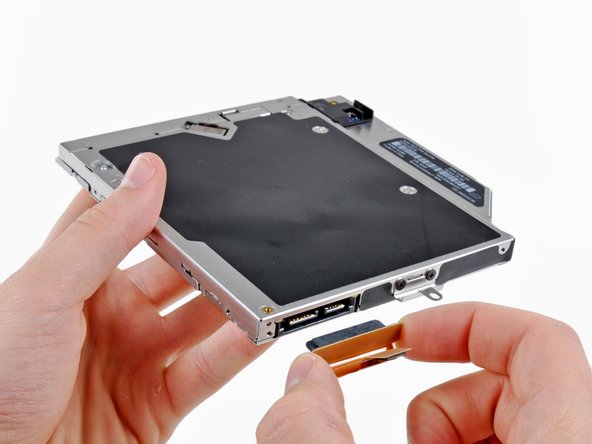
    • Grab the optical drive cable by its connector and pull it away from the body of the optical drive.

    • Pulling on anything other than the optical drive connector may damage the optical drive cable.

결승점

다른 9명이 해당 안내서를 완성하였습니다.

Andrew Bookholt

586,109 평판

안내서 619개 작성하였습니다

댓글 0개

댓글 쓰기

조회 통계:

24 시간 전: 5

7일 전: 7

30일 전: 9

전체 시간: 10,946