이 버전에는 잘못된 편집 사항이 있을 수 있습니다. 최신 확인된 스냅샷으로 전환하십시오.
필요한 것
-
이 단계는 번역되지 않았습니다. 번역을 도와주십시오
-
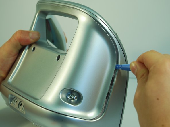
Remove the two plastic screw covers on the back of your Minimove by inserting the flat end of your plastic opening tool between the screw cover and the back panel and prying it out.
-
-
이 단계는 번역되지 않았습니다. 번역을 도와주십시오
-
Remove the four grey screw covers by inserting the plastic opening tool underneath the screw covers and rotating around the circumference.
-
-
이 단계는 번역되지 않았습니다. 번역을 도와주십시오
-
Remove the two 8 mm screws with a Phillips #1 screwdriver.
-
Remove the two 12 mm screws with a long Phillips #1 screwdriver.
-
-
이 단계는 번역되지 않았습니다. 번역을 도와주십시오
-
To remove the back panel, use the plastic opening tool and gently work around the outline of the panel. The outline wraps around the sides and can be spotted at the top back of the device.
-
-
이 단계는 번역되지 않았습니다. 번역을 도와주십시오
-
After loosening the panel with the plastic opening tool, use moderate force to pry open the panel with your hands.
-
Carefully pull the panel off.
-
-
-
이 단계는 번역되지 않았습니다. 번역을 도와주십시오
-
Use a Phillips #1 screwdriver to detach the wire from the back panel by removing the 8 mm screw connecting the wire to the antenna.
-
-
이 단계는 번역되지 않았습니다. 번역을 도와주십시오
-
If desired, the antenna can now be removed by pulling inwards and horizontal to the panel bottom.
-
-
이 단계는 번역되지 않았습니다. 번역을 도와주십시오
-
Use the Phillips #1 screwdriver to remove the four 12 mm screws.
-
Remove the five 6 mm screws at the top with the same screwdriver.
-
-
이 단계는 번역되지 않았습니다. 번역을 도와주십시오
-
Use a Phillips #1 screwdriver and remove the two vertical 8 mm screws from the top.
-
-
이 단계는 번역되지 않았습니다. 번역을 도와주십시오
-
Pry open the inner back panel by inserting the plastic opening tool in the crack at the top corner.
-
Use moderate force to pry it open and take the cover off.
-
-
이 단계는 번역되지 않았습니다. 번역을 도와주십시오
-
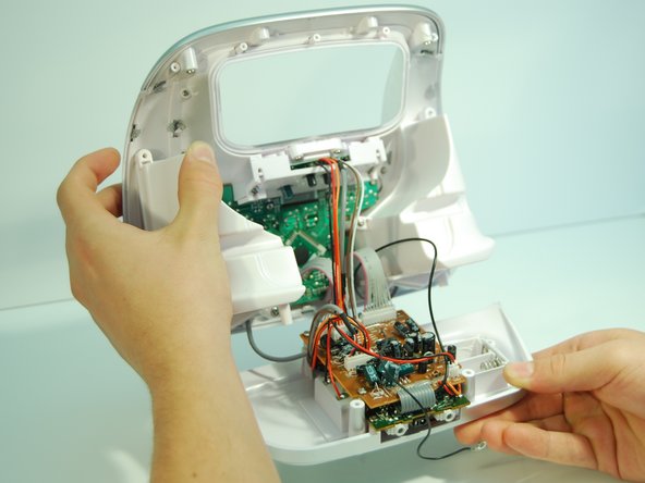
Remove the bottom panel of the boombox by carefully pulling the panel straight backwards from the boombox until the motherboard and daughterboard are free.
-
-
이 단계는 번역되지 않았습니다. 번역을 도와주십시오
-
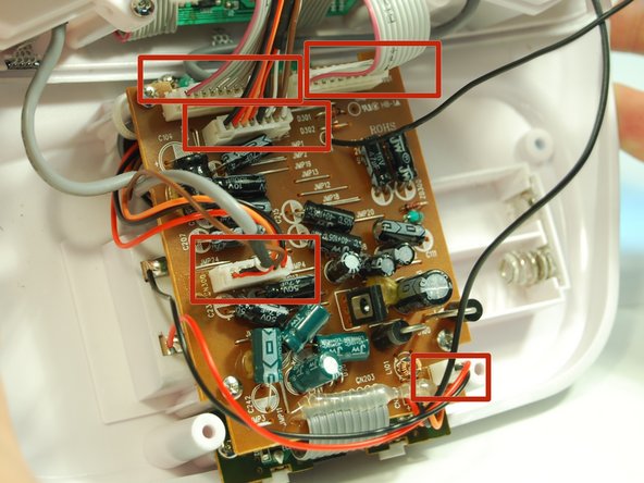
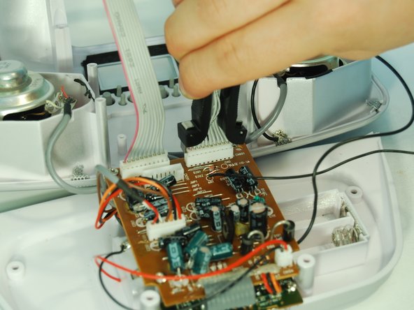
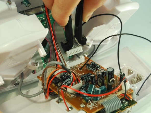
Pull out the 5 white pinhead connectors using an IC (Integrated Circuit) extractor. Pinch the IC extractor just under the top lip of the wire housing.
-
-
이 단계는 번역되지 않았습니다. 번역을 도와주십시오
-
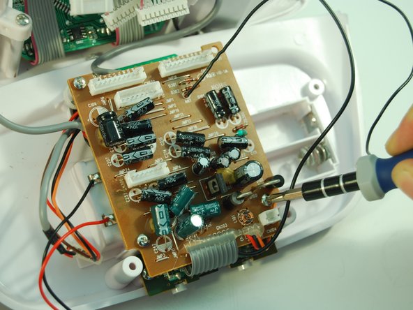
Use the Phillips #1 Screwdriver to remove the three 8 mm screws holding the motherboard in place.
-
-
이 단계는 번역되지 않았습니다. 번역을 도와주십시오
-
Detach the smaller green audio port daughterboard by removing the two 8 mm screws with a Phillips #1 screwdriver.
-
-
이 단계는 번역되지 않았습니다. 번역을 도와주십시오
-
Locate two wires, one red and one black, located on the left side of the battery pack.
-
-
이 단계는 번역되지 않았습니다. 번역을 도와주십시오
-
Heat up the soldering iron to around 600 Fahrenheit / 315 Celsius.
-
Place the tip of the soldering iron on the solder where the wire is connected and melt it until you can detach the wire.
-
Visit the soldering iron guide for more help with desoldering and soldering.
-
-
이 단계는 번역되지 않았습니다. 번역을 도와주십시오
-
After detaching the wire, move it away from the device.
-
Use a desoldering pump while the solder is still liquid to remove excess solder.
-


다른 3명이 해당 안내서를 완성하였습니다.

팀

Cal Poly, Team 2-9, Amido Winter 2014 Cal Poly, Team 2-9, Amido Winter 2014 회원
CPSU-AMIDO-W14S2G9
5 회원들
안내서 6개 작성하였습니다