주요 콘텐츠로 건너뛰기

Motorola MOTO W755 Cell Phone Main Logic Board Replacement

필요한 것

  1. Motorola MOTO W755 Cell Phone Main Logic Board Replacement, Battery: 1 단계, 이미지 1/2 Motorola MOTO W755 Cell Phone Main Logic Board Replacement, Battery: 1 단계, 이미지 2/2
    • Using your finger, press down on the clip holding the back cover on

    • Pull the back cover off.

  2. Motorola MOTO W755 Cell Phone Main Logic Board Replacement: 2 단계, 이미지 1/2 Motorola MOTO W755 Cell Phone Main Logic Board Replacement: 2 단계, 이미지 2/2
    • Place thumb and index finger in the spaces on either side of the battery.

    • Pull battery out.

  3. Motorola MOTO W755 Cell Phone Main Logic Board Replacement, Main Logic Board: 3 단계, 이미지 1/1
    • Using the T5 Torx-screwdriver, remove the four 5.5 mm screws on the back panel.

  4. Motorola MOTO W755 Cell Phone Main Logic Board Replacement: 4 단계, 이미지 1/2 Motorola MOTO W755 Cell Phone Main Logic Board Replacement: 4 단계, 이미지 2/2
    • Using a plastic opening tool, carefully peel back the rubber strip located at the bottom of the keypad

    • Remove the two T5 Torx-screws underneath the rubber strip using the T5 Torx-screwdriver

  5. Motorola MOTO W755 Cell Phone Main Logic Board Replacement: 5 단계, 이미지 1/3 Motorola MOTO W755 Cell Phone Main Logic Board Replacement: 5 단계, 이미지 2/3 Motorola MOTO W755 Cell Phone Main Logic Board Replacement: 5 단계, 이미지 3/3
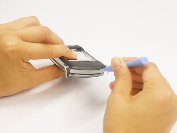
    • Using the flat end of the plastic opening tool, insert it in the gap between the charging port and plastic at the bottom left side of the phone.

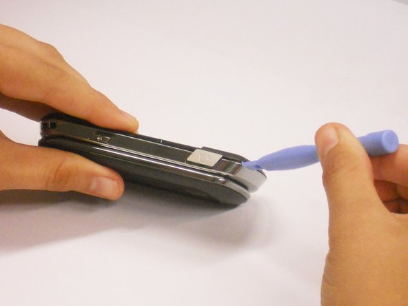
    • Slide the opening tool around the phone clockwise until you reach the audio port.

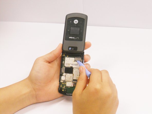
    • Twist the opening tool until the plastic pops off from the body of the phone. This make require a small amount of force.

  6. Motorola MOTO W755 Cell Phone Main Logic Board Replacement: 6 단계, 이미지 1/1
    • Remove the plastic covering completely from the body of the phone.

  7. Motorola MOTO W755 Cell Phone Main Logic Board Replacement: 7 단계, 이미지 1/2 Motorola MOTO W755 Cell Phone Main Logic Board Replacement: 7 단계, 이미지 2/2
    • Using the plastic opening tool, carefully unclip the cable ribbon from the main logic board. Be sure not to tear it because the flex is very fragile.

    • Remove the main logic board.

결론

To reassemble your device, follow these instructions in reverse order.

C Miller

회원 가입일: 06/25/12

56 평판

안내서 3개 작성하였습니다

Cal Poly, Team 1-3, Regan SU 2012 Cal Poly, Team 1-3, Regan SU 2012 회원

CPSU-REGAN-SU12S1G3

2 회원들

안내서 14개 작성하였습니다

댓글 0개

댓글 쓰기

조회 통계:

24 시간 전: 1

7일 전: 1

30일 전: 1

전체 시간: 1,501