필요한 것
-
이 단계는 번역되지 않았습니다. 번역을 도와주십시오
-
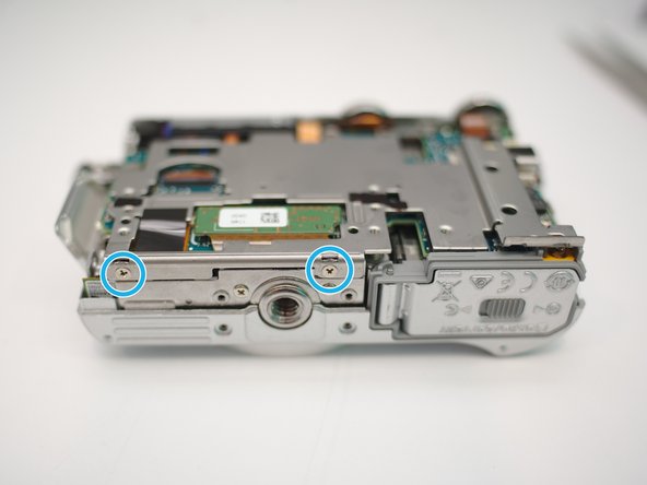
Remove 2 screws first
-
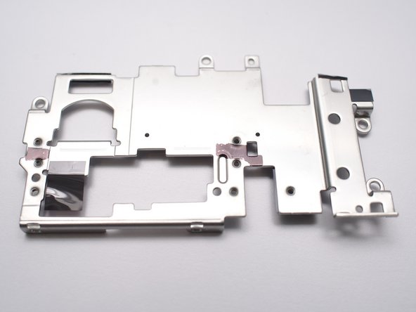
Lift the cover
-
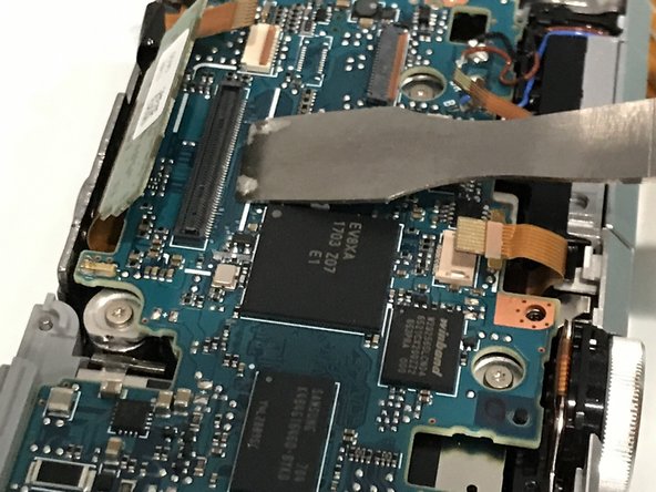
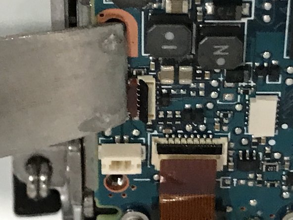
Disconnect LCD FPC
-
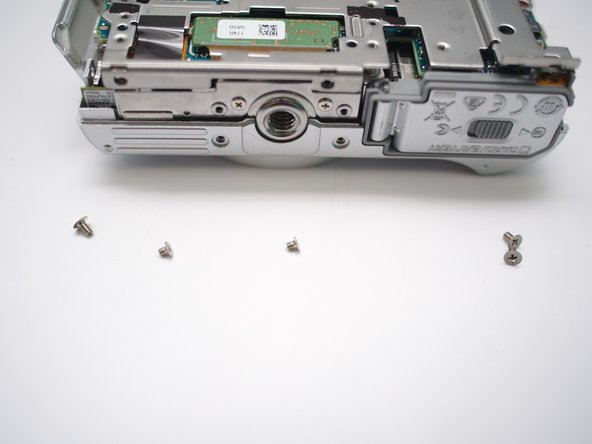
Then remove 4 screws
-
Remove LCD assembly
-
-
이 단계는 번역되지 않았습니다. 번역을 도와주십시오
-
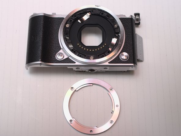
Remove 4 screws and be ware the length difference
-
Peel the rubber open from right hand side
-
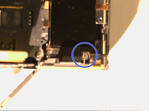
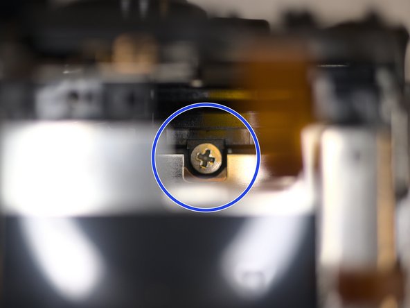
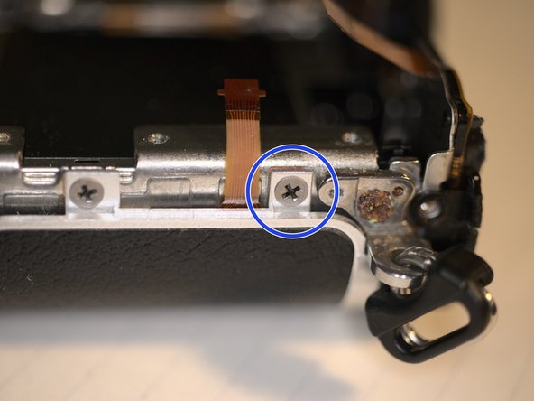
Remove 1 screw
-
-
이 단계는 번역되지 않았습니다. 번역을 도와주십시오
-
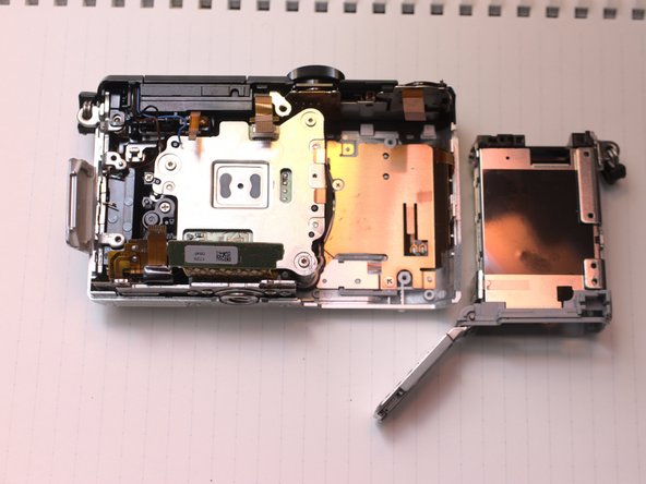
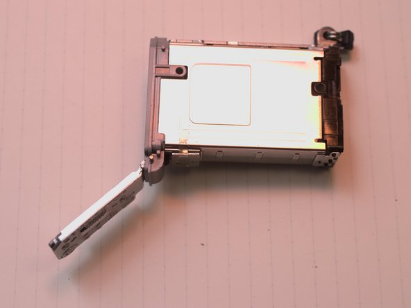
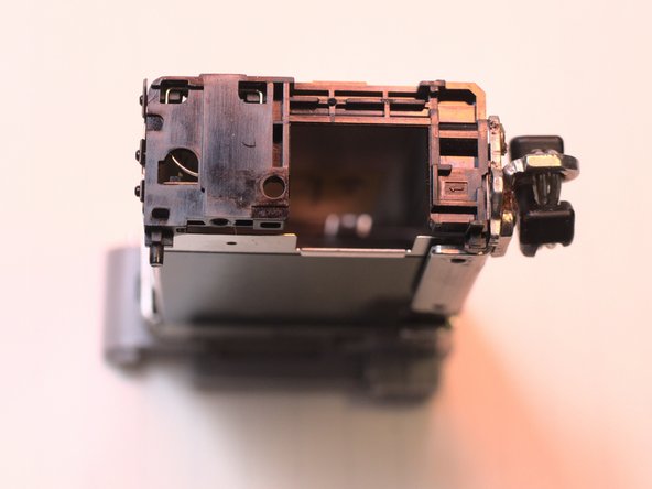
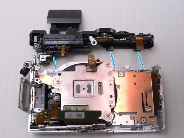
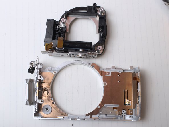
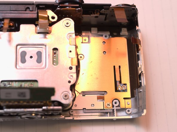
Now the back case can be removed.
-
There's no fragile FPC or cables in this step. Just be patient.
-
-
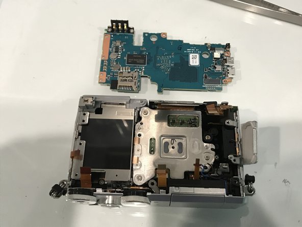
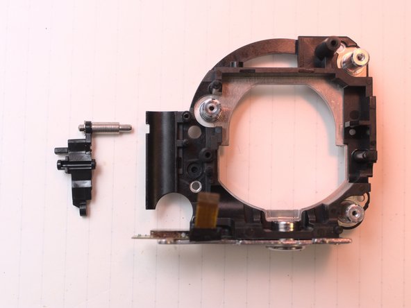
이 단계는 번역되지 않았습니다. 번역을 도와주십시오
-
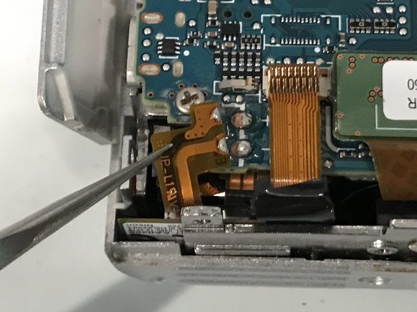
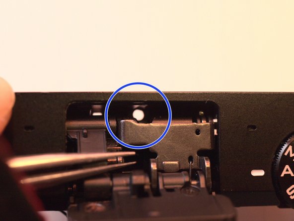
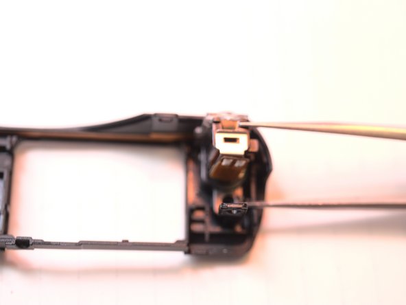
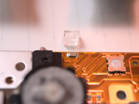
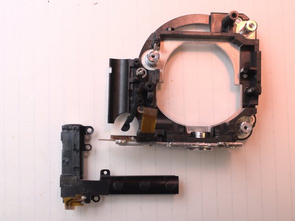
Insert small crowbar or flat head screw driver here to lift the keypad up.
-
-
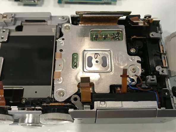
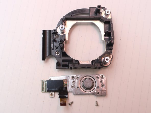
이 단계는 번역되지 않았습니다. 번역을 도와주십시오
-
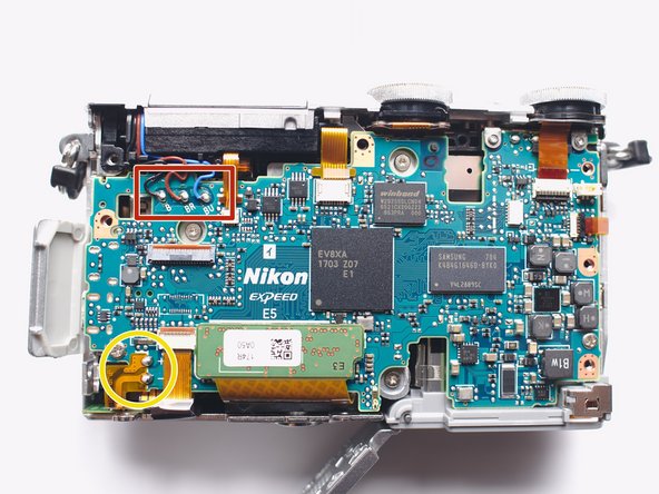
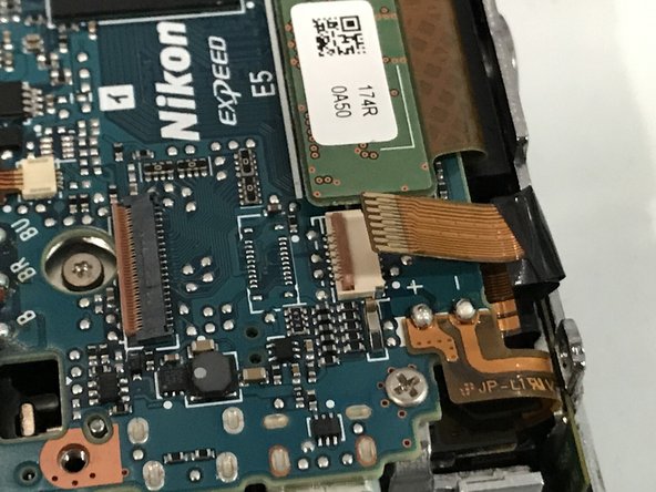
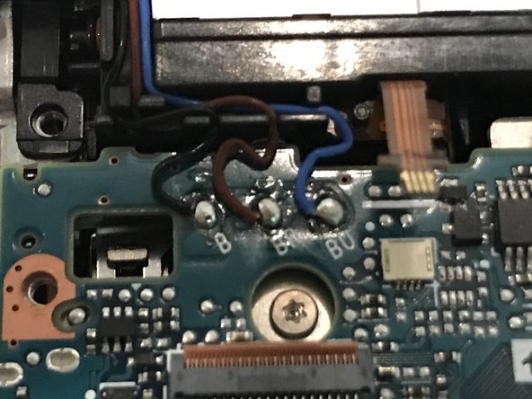
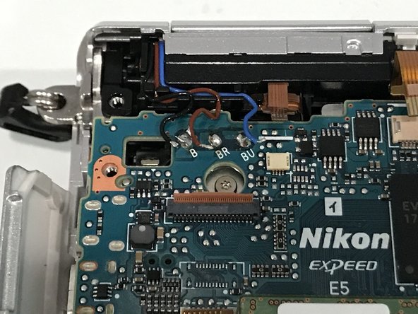
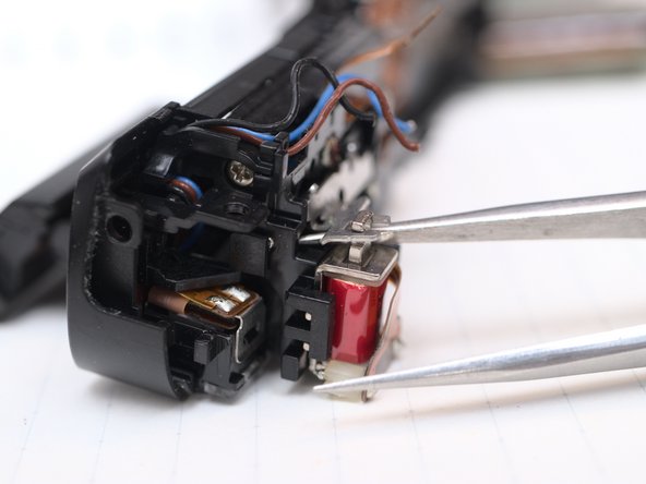
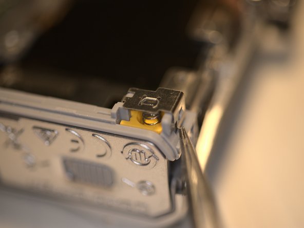
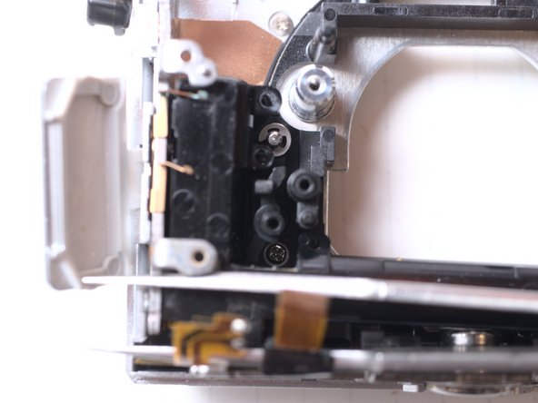
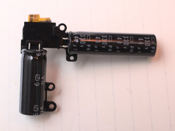
Flash xenon tube terminals, positive connected to capacitor, negative controlled by circuit, and a trigger signal.
-
Use 10kohm, >2W resistor, connect 2 solder joints for more than 5sec. These are flash condenser/capacitor terminals. DO NOT discharge by SHORT them. (Note 2020-10-13)
-
-
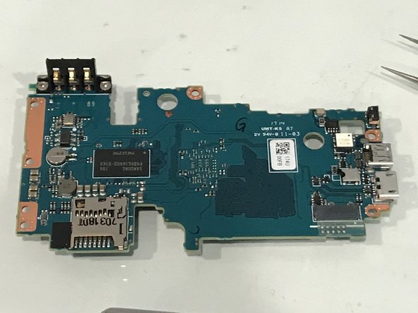
이 단계는 번역되지 않았습니다. 번역을 도와주십시오
-
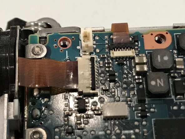
Flash solenoid and detecter
-
Microphones and AF assistant LED
-
Keypad
-
Switches
-
NFC
-
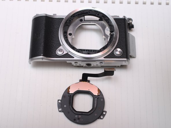
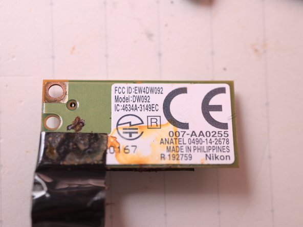
WiFi and Bluetooth, Lens(back)
-
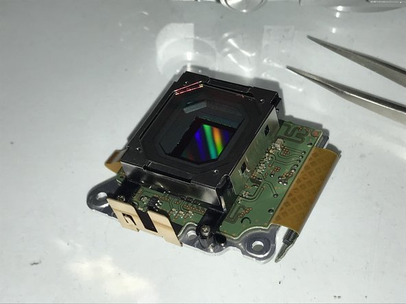
CMOS sensor
-
LCD
-
-
-
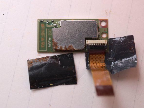
이 단계는 번역되지 않았습니다. 번역을 도와주십시오
-
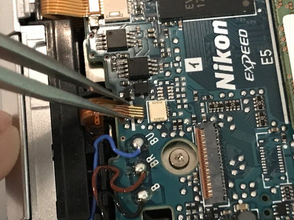
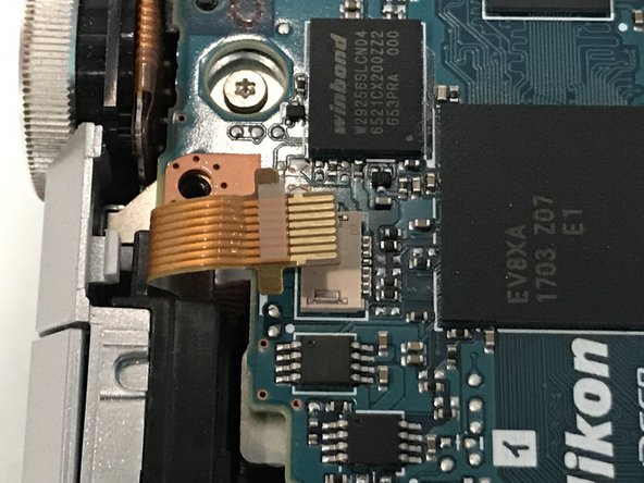
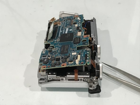
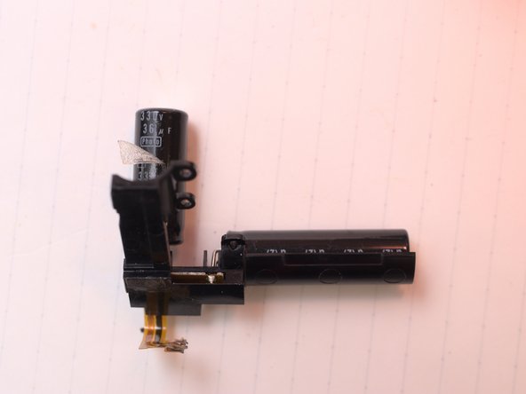
Desolder flash condenser FPC and Flash cables (remember to discharge first)
-
-
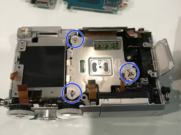
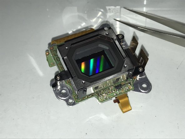
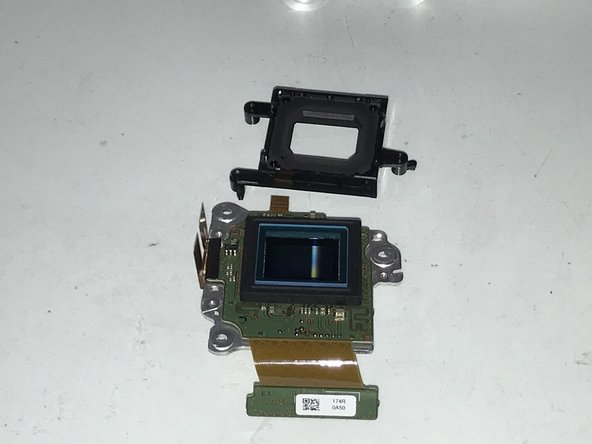
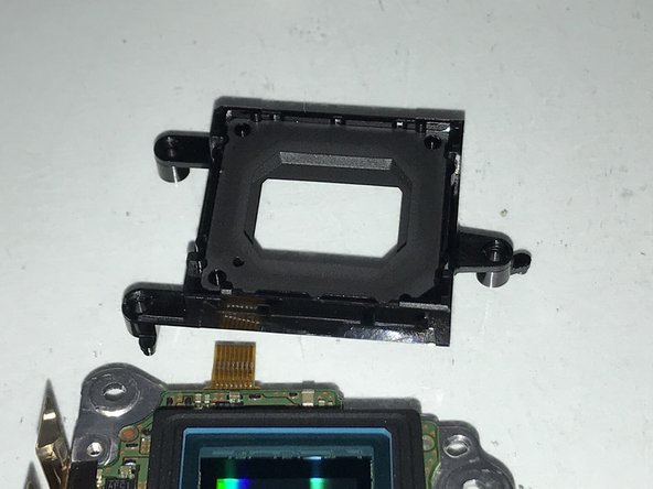
이 단계는 번역되지 않았습니다. 번역을 도와주십시오
-
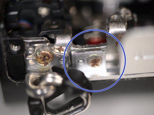
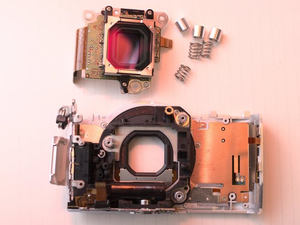
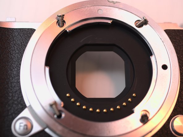
Mark 3 screws for their ID and position.
-
Also record how many turns to the limit.
-
Measure and record distance to front flange if possible.
-
-
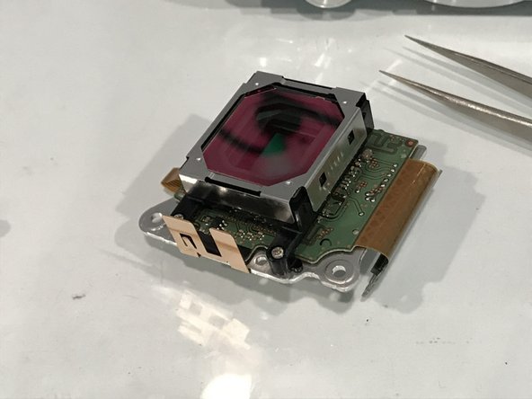
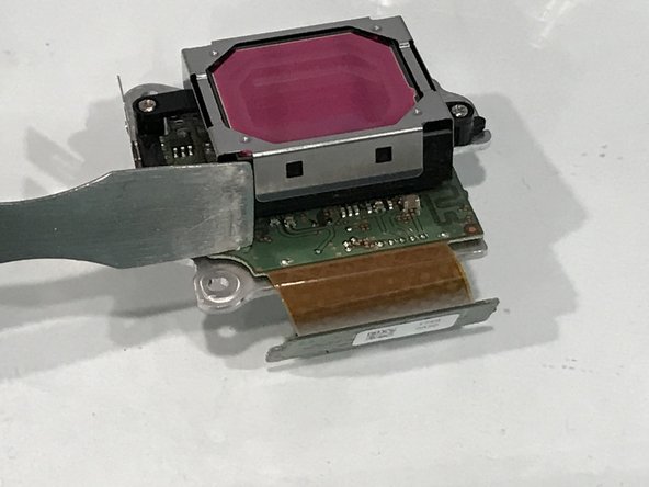
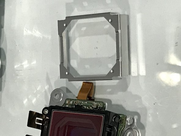
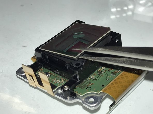
이 단계는 번역되지 않았습니다. 번역을 도와주십시오
-
Hold the IR-cut filter by its edge, to avoid scratches and contamination.
-
Use plastic tweezers can avoid scratches.
-
-
이 단계는 번역되지 않았습니다. 번역을 도와주십시오
-
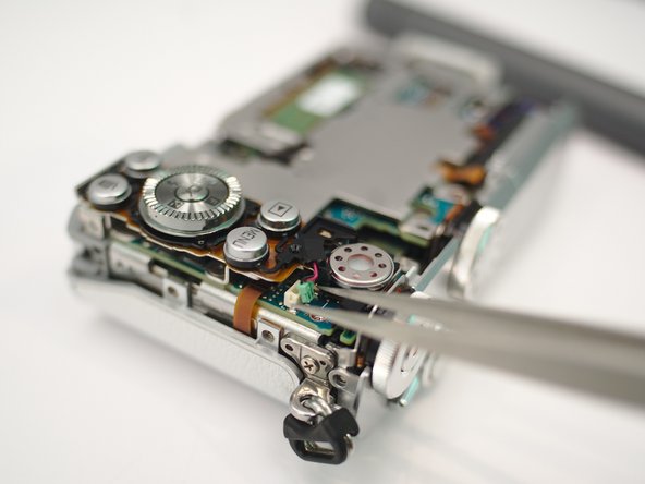
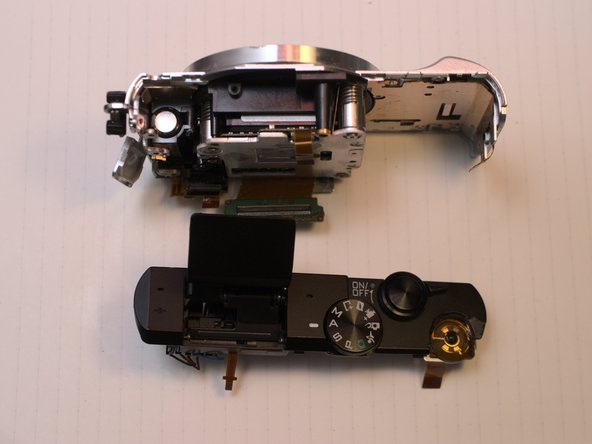
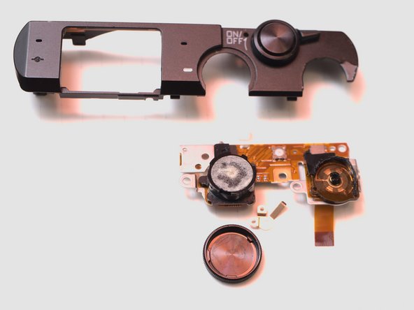
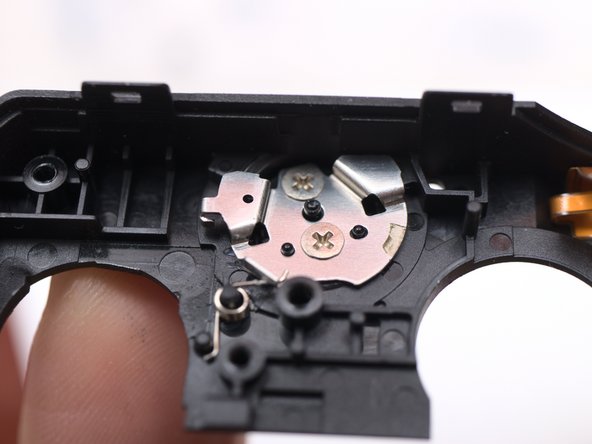
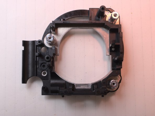
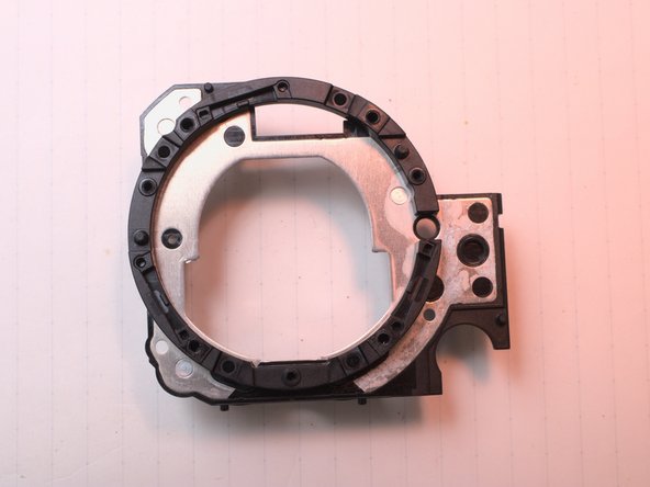
Top Case
-
AF assistant LED and left Microphone
-
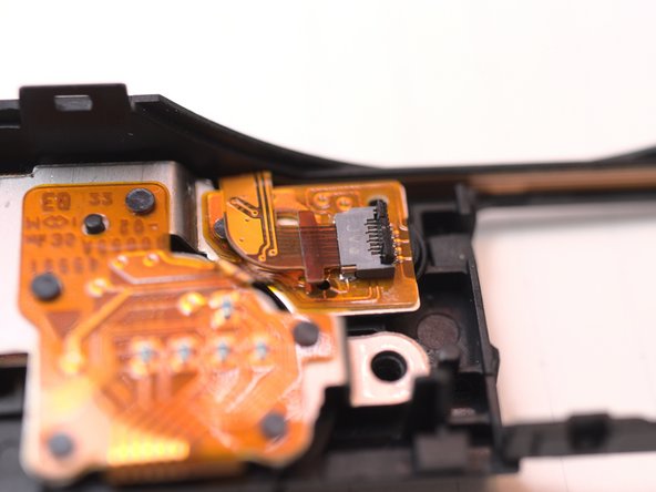
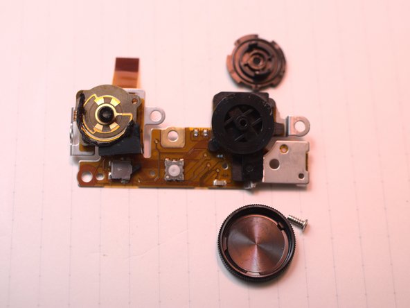
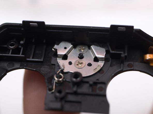
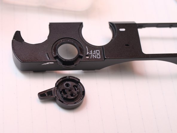
Switch board. Right microphone, power switch, shutter button, mode dial, main command dial.
-
-
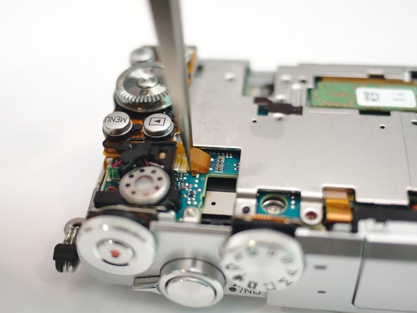
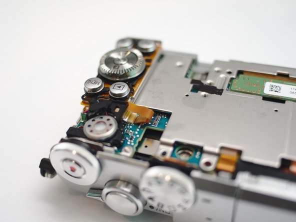
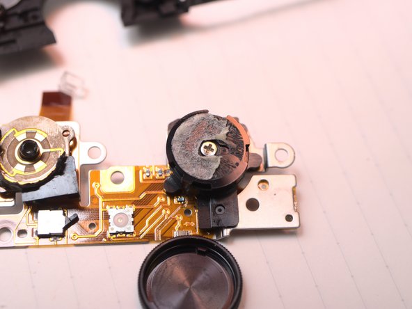
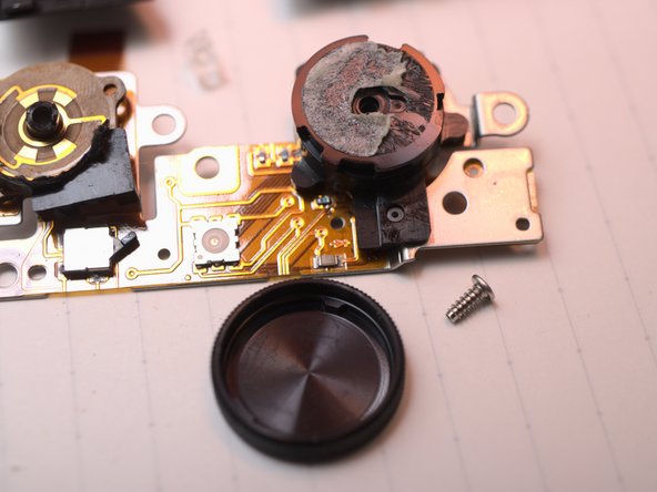
이 단계는 번역되지 않았습니다. 번역을 도와주십시오
-
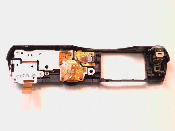
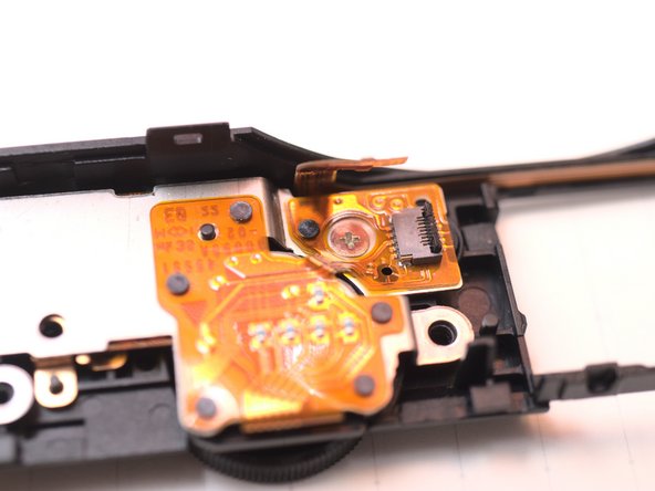
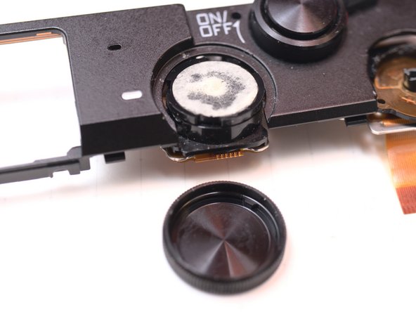
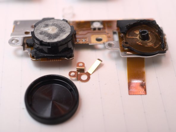
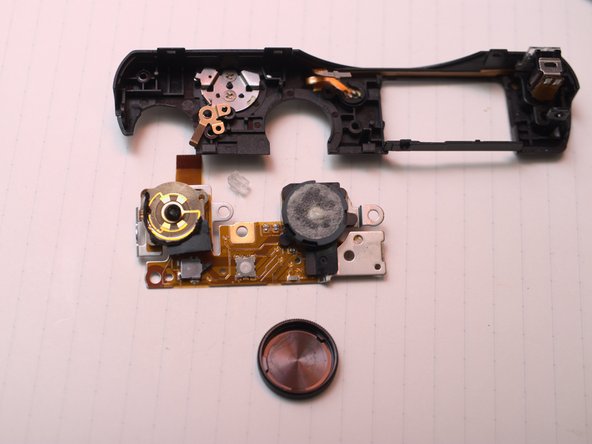
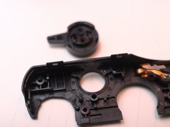
Mode dial cap is double sided taped,
-
Remove switch board.
-
Someone else already murdered the main dial and video record button...
-
-
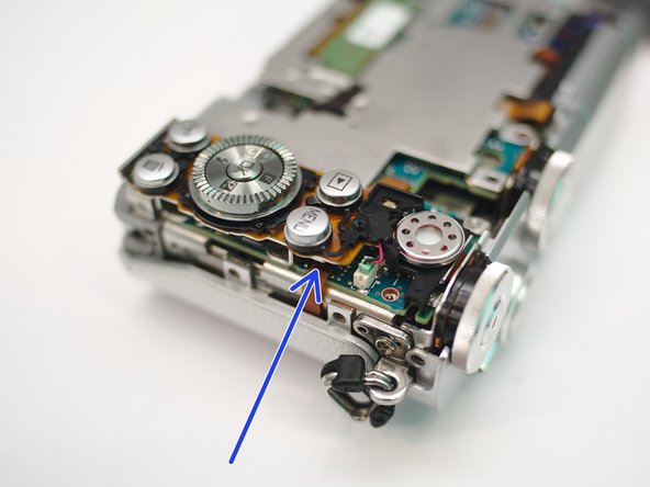
이 단계는 번역되지 않았습니다. 번역을 도와주십시오
-
Focus adjust and focal plane calibration is important to par-focal lenses
-


댓글 12개
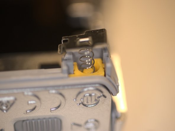
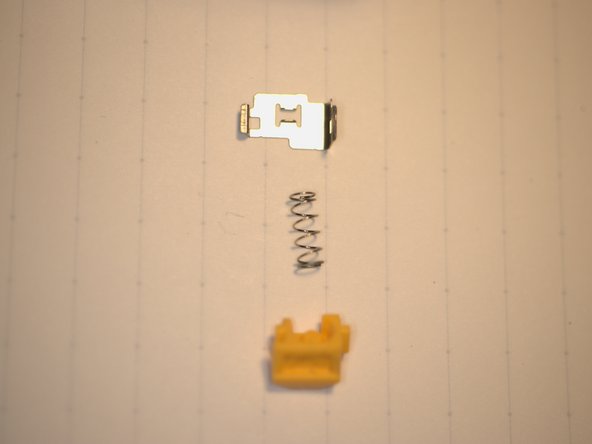
Hi Terrance - the return spring on the on/off switch has gone on mine - are you able to see how to get at this on your stripped down one?
freecycle at evendine dot eclipse dot co dot uk in case I don’t notice it coming up here
hmm, haven’t dug that deep yet… The front case disassembly seems very tricky. Also the IR-cut removal.
Terrance -
Sorry to hear that, I arrive here coming for a solution for the return spring on the on/off switch, is not a big problem but a pain and battery drain if you don’t realise :)
Anyway thanks for your teardown really formative.
I tried to remove the top cover to repair the return spring on the ON/OFF, but I was not able to separate it from the body. I have no solution.
I finally got my hands on a wasted 1J5 and go on with the tear down. FYI top cover is sort of easy to remove, but very tricky. post more photos later.
I some simple words, after removing main PCB, remove some screws from left-upper right-upper and inside flash bay,you can wiggle the top clean off.
And, the power switch is berried very deep. you have to fond all sneaky screws. Aaaaaand the mode dial cap is double-side-taped, some thermal energy needed.
Terrance -