이 버전에는 잘못된 편집 사항이 있을 수 있습니다. 최신 확인된 스냅샷으로 전환하십시오.
필요한 것
-
이 단계는 번역되지 않았습니다. 번역을 도와주십시오
-
Place the 3DS upside down. Remove the game card, headphones, charging cable, stylus, or anything else that may be connected to the device.
-
-
이 단계는 번역되지 않았습니다. 번역을 도와주십시오
-
The battery is located on the left hand side of the 3DS - to remove, use the small gap located at the top-middle and pull up with a non metal pointed tool.
-
-
이 단계는 번역되지 않았습니다. 번역을 도와주십시오
-
Using a JIS #000 screwdriver, remove the six 6mm screws around the edges of the secondary cover.
-
-
-
이 단계는 번역되지 않았습니다. 번역을 도와주십시오
-
Using tweezers, carefully pop out the rubber bumpers located at the top side of the 3DS. Removing them will reveal another two 6mm screws. Remove these screws using a JIS #000 as well.
-
-
이 단계는 번역되지 않았습니다. 번역을 도와주십시오
-
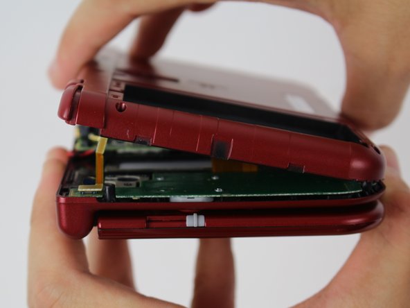
To separate the cover, carefully lift it up and away from the hinges (in order to clear the headphone port), then pivot it towards the hinges to expose the circuit boards.
-
-
이 단계는 번역되지 않았습니다. 번역을 도와주십시오
-
Use a pair of tweezers to lift away the two plugs that latch the L/R/ZL/ZR button ribbons to the motherboard. You can now remove the back cover completely and set it aside.
-
-
이 단계는 번역되지 않았습니다. 번역을 도와주십시오
-
Use tweezers to flip up the small, hinged locking flap in order to unlock the ZIF connector securing the circle pad ribbon.
-
Slide the ribbon out of the ZIF connector.
-
-
이 단계는 번역되지 않았습니다. 번역을 도와주십시오
-
Using a JIS #000 screwdriver, remove the two 8 mm screws securing the circle pad.
-
-
이 단계는 번역되지 않았습니다. 번역을 도와주십시오
-
Lift the circle pad casing upward to remove it. There will be some friction, but it should not require excessive force.
-
-
이 단계는 번역되지 않았습니다. 번역을 도와주십시오
-
Locate the gold terminal plug with a red cable at the top left of the motherboard. Using your fingers, carefully pull the plug straight upward to remove.
-
Use a pair of tweezers to disconnect the single ribbon connector.
-
-
이 단계는 번역되지 않았습니다. 번역을 도와주십시오
-
Using tweezers, gently pull the five marked ribbons out of the ZIF connectors along the sides of the motherboard.
-
Three of the ribbon connectors have plastic clamping flaps that cover the ribbon to prevent slippage. Use the tweezers to flip them up before ribbon removal.
-
-
이 단계는 번역되지 않았습니다. 번역을 도와주십시오
-
Using a JIS #000 screwdriver, remove six 4mm screws along the edges of the motherboard.
-
-
이 단계는 번역되지 않았습니다. 번역을 도와주십시오
-
Carefully pivot the motherboard 90 degrees toward the hinges to reveal two more ZIF connectors on the underside of the motherboard.
-
Both have latches that must be flipped up. The left, longer latch is black; the right, shorter one is white. Flip up the flaps, slide the ribbons out and remove the motherboard.
-


다른 48명이 해당 안내서를 완성하였습니다.

팀

Cal Poly, Team 24-4, Lancaster Spring 2015 Cal Poly, Team 24-4, Lancaster Spring 2015 회원
CPSU-LANCASTER-S15S24G4
4 회원들
안내서 25개 작성하였습니다
댓글 11개
With some digging, I managed to find this on the GBAtemp forums , which host a community of 3DS modders:
https://gbatemp.net/threads/screwed-up-p...
Seems like no one's quite sure, but it could be a start. Unfortunately, the N3DS components are largely small black boxes with no labeling.
If you have a multimeter, it might help to test some of these mystery boxes.
Question: Seeing as how you pulled the red cable in the photos, how was that fixed? Asking for a friend.
We...never fixed that actually, as we didn't have the tools for it and the device had been loaned to us specifically for tearing down.
I don't know if iFixit themselves ever did anything with it, but I would imagine soldering the frayed end of the cable back onto the plug would work. (Here's a guide on that: http://www.instructables.com/id/Solderin... )