이 버전에는 잘못된 편집 사항이 있을 수 있습니다. 최신 확인된 스냅샷으로 전환하십시오.
필요한 것
-
이 단계는 번역되지 않았습니다. 번역을 도와주십시오
-
Place your device upside down and locate the battery compartment.
-
Find the Phillips head screw securing the battery cover in the bottom right hand corner of the device.
-
-
이 단계는 번역되지 않았습니다. 번역을 도와주십시오
-
Use the iFixit opening tool to carefully pry the battery out of the case.
-
After the old battery is removed replace it with a new battery facing the same direction as when the cover was opened.
-
-
이 단계는 번역되지 않았습니다. 번역을 도와주십시오
-
Remove the following seven screws that secure the lower case to the DS Lite:
-
Three silver tri-wing screws (5mm long)
-
One black tri-wing screw (4mm)
-
Two gold Phillips screws (4mm)
-
One silver Phillips screw (3mm)
-
Do not remove the silver PH screw (3mm) in the battery compartment yet. It holds the main PCB in place.
-
-
이 단계는 번역되지 않았습니다. 번역을 도와주십시오
-
On the front edge of the Nintendo DS between the headphone jack plug and volume controls remove the plastic insert (or cartridge) from the lower slot (Slot 2).
-
-
이 단계는 번역되지 않았습니다. 번역을 도와주십시오
-
Flip the unit over so that it is facing right-side up.
-
Use a spudger to pry open the gap between the bottom case and the front panel. Work all the way around the case until the panel is free.
-
Avoid touching the L and R shoulder buttons, because they easily detach and are difficult to reassemble. Keep the bottom case flat against your workbench to help hold the shoulder buttons in place.
-
-
이 단계는 번역되지 않았습니다. 번역을 도와주십시오
-
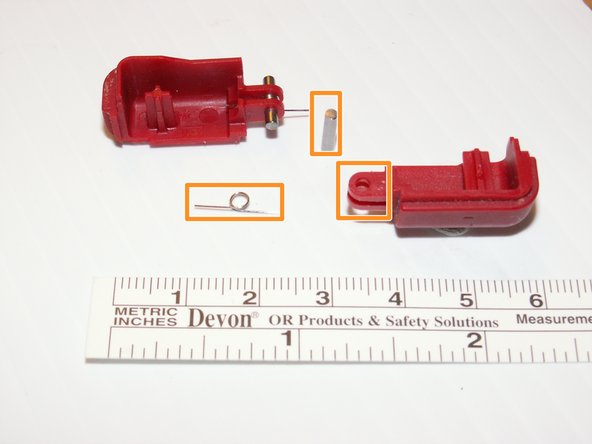
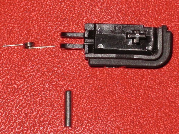
Carefully separate the two pieces by hand.
-
The two shoulder buttons are made up of three pieces -- the plastic button, a pin, and a spring. If they accidentally pop out while you are working, study the picture and make sure you put the spring in the correct position.
-
-
-
이 단계는 번역되지 않았습니다. 번역을 도와주십시오
-
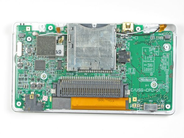
Locate the two screws that attach the logic board to the device.
-
Unscrew the two Phillips head screws.
-
-
이 단계는 번역되지 않았습니다. 번역을 도와주십시오
-
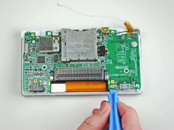
With a plastic opening tool, gently separate the logic board from the device base.
-
-
이 단계는 번역되지 않았습니다. 번역을 도와주십시오
-
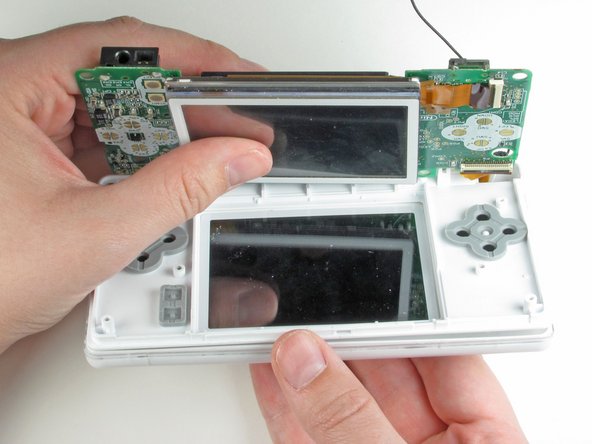
Flip the logic board over so that the touch screen is facing up.
-
Using metal tweezers, carefully disconnect the other ribbon cable that connects the touch screen with the logic board.
-
-
이 단계는 번역되지 않았습니다. 번역을 도와주십시오
-
Using one finger nail or the plastic opening tool, carefully lift the brown securing flap of the connector. Then disconnect the ribbon cable that connects the logic board to the upper screen.
-
-
이 단계는 번역되지 않았습니다. 번역을 도와주십시오
-
Remove the two Phillips-head screws that hold the hinge in place.
-
Open the system up (just like if you were about to use it normally).
-
-
이 단계는 번역되지 않았습니다. 번역을 도와주십시오
-
After opening it, carefully unhinge them from each other by sliding the bottom piece to the left and the top piece to the right.
-
-
이 단계는 번역되지 않았습니다. 번역을 도와주십시오
-
Using a push pin, remove the four rubber bumpers located at the corners of the top screen.
-
After removing the LEDs and pulling apart the hinge, remove the round hinge shaft. This should be in the top screen piece.
-
-
이 단계는 번역되지 않았습니다. 번역을 도와주십시오
-
Carefully remove the two speakers and the green wireless card from the top panel.
-
-
이 단계는 번역되지 않았습니다. 번역을 도와주십시오
-
Remove the screen by orienting it face down and pushing up on the screen from underneath.
-
-
이 단계는 번역되지 않았습니다. 번역을 도와주십시오
-
The speakers are soldered to the top screen flex assembly. You may desolder a broken speaker and solder a working speaker on, or you may replace the speakers together with the display assembly.
-


다른 한 분이 해당 안내서를 완성하였습니다.
팀

Cal Poly, Team 16-30, Maness Winter 2010 Cal Poly, Team 16-30, Maness Winter 2010 회원
CPSU-MANESS-W10S16G30
4 회원들
안내서 24개 작성하였습니다