주요 콘텐츠로 건너뛰기

이 버전에는 잘못된 편집 사항이 있을 수 있습니다. 최신 확인된 스냅샷으로 전환하십시오.

Nintendo Switch Pro Controller Joystick 모듈 교체

필요한 것

  1. Nintendo Switch Pro Controller Joystick 모듈 교체, 나사 풀기: 1 단계, 이미지 1/1
    • 모델 스티커가 천장을 향하도록 컨트롤러를 뒤집으세요.

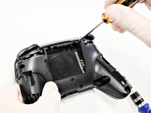
    • JIS #00 스크루드라이버를 사용하여 손잡이 끝에 손잡이를 고정하는 검정색 8.4mm 나사 2개를 풀어주세요.

  2. Nintendo Switch Pro Controller Joystick 모듈 교체, 손잡이 커버 분리하기: 2 단계, 이미지 1/3 Nintendo Switch Pro Controller Joystick 모듈 교체, 손잡이 커버 분리하기: 2 단계, 이미지 2/3 Nintendo Switch Pro Controller Joystick 모듈 교체, 손잡이 커버 분리하기: 2 단계, 이미지 3/3
    • 손잡이 커버를 본체에서 당겨 조심히 분리하세요.

  3. Nintendo Switch Pro Controller Joystick 모듈 교체, 나사 풀기: 3 단계, 이미지 1/1
    • JIS #00 드라이버를 사용하여 투명한 후면 플라스틱 덮개를 고정하는 은색 6.8mm 나사 네 개를 풀어주세요.

  4. Nintendo Switch Pro Controller Joystick 모듈 교체, 플라스틱 덮개 클립 풀기: 4 단계, 이미지 1/3 Nintendo Switch Pro Controller Joystick 모듈 교체, 플라스틱 덮개 클립 풀기: 4 단계, 이미지 2/3 Nintendo Switch Pro Controller Joystick 모듈 교체, 플라스틱 덮개 클립 풀기: 4 단계, 이미지 3/3
    • 손톱을 사용하여 투명한 플라스틱 덮개를 조심히 들어 올리세요.

  5. Nintendo Switch Pro Controller Joystick 모듈 교체, 투명한 플라스틱 덮개 분리하기: 5 단계, 이미지 1/1
    • 투명한 플라스틱 덮개를 분리하세요.

  6. Nintendo Switch Pro Controller Joystick 모듈 교체, 배터리 분리하기: 6 단계, 이미지 1/3 Nintendo Switch Pro Controller Joystick 모듈 교체, 배터리 분리하기: 6 단계, 이미지 2/3 Nintendo Switch Pro Controller Joystick 모듈 교체, 배터리 분리하기: 6 단계, 이미지 3/3
    • 손톱이나 플라스틱 여는 도구를 사용하여 리튬 이온 배터리 왼편 가장자리를 들어 올려 분리하세요.

    • 약간의 힘만 있으면 됩니다.

  7. Nintendo Switch Pro Controller Joystick 모듈 교체, 나사 풀기: 7 단계, 이미지 1/3 Nintendo Switch Pro Controller Joystick 모듈 교체, 나사 풀기: 7 단계, 이미지 2/3 Nintendo Switch Pro Controller Joystick 모듈 교체, 나사 풀기: 7 단계, 이미지 3/3
    • Phillips/십자 #1 드라이버를 사용하여 컨트롤러 후면에서 5mm 나사 다섯 개를 풀어주세요.

    • 손잡이 위의 케이스 나사 2개와 배터리 베이 아래의 케이스 나사 1개는 얕은 위치에 있습니다. 이 나사 세 개는 쉽게 풀 수 있습니다.

    • ZRZL 숄더 버튼 옆에 있는 케이스 나사 두 개는 깊이가 깊습니다. 이 나사에 접근하려면 연장 또는 샤프트가 긴 십자 드라이버를 사용하세요.

  8. Nintendo Switch Pro Controller Joystick 모듈 교체: 8 단계, 이미지 1/3 Nintendo Switch Pro Controller Joystick 모듈 교체: 8 단계, 이미지 2/3 Nintendo Switch Pro Controller Joystick 모듈 교체: 8 단계, 이미지 3/3
    • 컨트롤러의 플라스틱 커버를 조심히 떼어내세요.

    • 전면 커버는 흰색 리본 케이블을 통해 마더보드에 여전히 부착되어 있으므로 아직 완전히 분리하지 마세요.

  9. Nintendo Switch Pro Controller Joystick 모듈 교체, 플랩 열기: 9 단계, 이미지 1/2 Nintendo Switch Pro Controller Joystick 모듈 교체, 플랩 열기: 9 단계, 이미지 2/2
    • 여는 픽의 끝을 사용하여 ZIF 커넥터의 검은색 플랩을 위쪽으로 밀어 여세요.

  10. Nintendo Switch Pro Controller Joystick 모듈 교체, 인터커넥트 케이블 연결 해제하기: 10 단계, 이미지 1/2 Nintendo Switch Pro Controller Joystick 모듈 교체, 인터커넥트 케이블 연결 해제하기: 10 단계, 이미지 2/2
    • 손가락이나 뭉툭한 핀셋을 사용하여 커넥터에서 인터커넥트 케이블을 분리하세요.

  11. Nintendo Switch Pro Controller Joystick 모듈 교체, 전면 케이스 분리하기: 11 단계, 이미지 1/1
    • 전면 케이스를 분리하세요.

  12. 이 단계는 번역되지 않았습니다. 번역을 도와주십시오

    Nintendo Switch Pro Controller Joystick 모듈 교체: 12 단계, 이미지 1/3 Nintendo Switch Pro Controller Joystick 모듈 교체: 12 단계, 이미지 2/3 Nintendo Switch Pro Controller Joystick 모듈 교체: 12 단계, 이미지 3/3
    • With light force pull the two joystick caps off of the controller.

  13. Nintendo Switch Pro Controller Joystick 모듈 교체, 마더보드 나사 풀기: 13 단계, 이미지 1/1
    • Philips/십자 스크루드라이버를 사용하여 마더보드를 고정하는 5mm-길이 나사 네 개를 풀어주세요.

  14. Nintendo Switch Pro Controller Joystick 모듈 교체, LED 라이트 분리하기: 14 단계, 이미지 1/3 Nintendo Switch Pro Controller Joystick 모듈 교체, LED 라이트 분리하기: 14 단계, 이미지 2/3 Nintendo Switch Pro Controller Joystick 모듈 교체, LED 라이트 분리하기: 14 단계, 이미지 3/3
    • 손톱 또는 핀셋을 사용하여 슬롯에서 LED 라이트를 빼세요.

    • 재조립을 대비해서 LED 라이트를 해당 나사와 함께 잘 보관하세요.

  15. Nintendo Switch Pro Controller Joystick 모듈 교체, 회로판 느슨하게 하기: 15 단계, 이미지 1/3 Nintendo Switch Pro Controller Joystick 모듈 교체, 회로판 느슨하게 하기: 15 단계, 이미지 2/3 Nintendo Switch Pro Controller Joystick 모듈 교체, 회로판 느슨하게 하기: 15 단계, 이미지 3/3
    • 회로판 오른편 하단 모서리를 살살 당겨서 회로판을 섀시에서 느슨하게 하세요.

    • 회로판을 들어 올려서 후면을 노출시키세요.

    • 전선 손상을 방지하기 위해서 회로판을 들어 올릴 때 너무 많은 힘을 가하지 마세요.

  16. Nintendo Switch Pro Controller Joystick 모듈 교체, 조이스틱 모듈 납땜 제거하기: 16 단계, 이미지 1/2 Nintendo Switch Pro Controller Joystick 모듈 교체, 조이스틱 모듈 납땜 제거하기: 16 단계, 이미지 2/2
    • 납땜 이음에 확실히 접근하기 위해서 회로판 후면을 보세요.

    • 테두리 안의 모든 납땜 이음을 납땝 제거하세요.

    • 회로판에서 조이스틱 모듈을 분리하세요.

    • 필요하다면, 다음 납땜 안내서를 참조하세요: 연결 부분 납땜 및 납땜 제거하는 방법

결론

기기를 재조립하려면, 이 지침들을 역순으로 따르세요.

다른 36명이 해당 안내서를 완성하였습니다.

다음 번역가들에게 특별히 감사 드립니다:

en ko

100%

Christian Kim님은 저희가 세상을 수리하는데 동참하신 분입니다! 기여하시겠습니까?
번역 시작하기 ›

Daniel Tagalog

회원 가입일: 10/10/19

1,592 평판

안내서 3개 작성하였습니다

Cal Poly, Team S11-G2, Regan Fall 2019 Cal Poly, Team S11-G2, Regan Fall 2019 회원

CPSU-REGAN-F19S11G2

5 회원들

안내서 42개 작성하였습니다

댓글 24개

I managed to replace mine with much difficulty with the soldering but the stick does not seem to turn fully anymore, both with the replacement and the original. For reference, when I go to test it, it no longer registers as reaching the outer circle when pressed all the way down. Similarly when I go to calibrate it, it only reaches up til about the 2nd outer circle, not enough to actually trigger the green arrow. Since this seems to occur on both the replacement and original stick now, I’m guessing this must be some issue that arose while I was struggling with the desoldering process. Anybody have any ideas what might be causing my issue? Have I just damaged it beyond repair?

Tyler - 답글

Without pictures it is impossible to tell, but there is the possibility that you strips the metal connection on the solder point. This is fixable by “bridging” the connection. You will want to find schematics of the wiring for the PCB and then solder the wire over to the next connection.

As a side note, I should mention that I have never tried this on a controller of any sort and that I have only used this method on keyboards with single wire connections. It is possible that the connection in a controller PCB have more going on and that this technique will not work.

Gavin A -

I have the same problem, I buy 2 joystick module from iFixit and the two gave me the same issue, the joystick module don't reach the green arrow.

I can't calibrate because of that issue.

Any ideas?

Piero Grasso -

I have also had the same issue with replacement, only reaches roughly 75%. I contacted ifixit and they sent me a replacement thinking it might be a faulty pot, I installed the new stick and have the same issue. Maybe different years used different resistance.

marcos aguilera -

See my answer a bit down. I think it has to do with the resistance of the module. I had the same issue with the part I received from iFixit, the original part has a resistance of 1150 ohm, but the replacement is 1600 ohm. And I have a different module which is about 500 ohm, and that works just fine.

Peter de Bruine -

댓글 쓰기

조회 통계:

24 시간 전: 54

7일 전: 455

30일 전: 1,872

전체 시간: 106,489