이 버전에는 잘못된 편집 사항이 있을 수 있습니다. 최신 확인된 스냅샷으로 전환하십시오.
필요한 것
-
이 단계는 번역되지 않았습니다. 번역을 도와주십시오
-
Unscrew all immediately visible screws on the body of the camera.
-
Locations (# of screws): Bottom of camera (3), left side near video port (2), under cover of USB slot (3), memory card slot (1).
-
-
이 단계는 번역되지 않았습니다. 번역을 도와주십시오
-
Use the plastic opening tool to separate the back cover from the camera.
-
-
이 단계는 번역되지 않았습니다. 번역을 도와주십시오
-
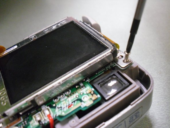
With the back plate off, locate two screws: one diagonal from the top left of the LCD screen and one diagonal from the top right of the LCD screen.
-
Unscrew both of these screws.
-
-
-
이 단계는 번역되지 않았습니다. 번역을 도와주십시오
-
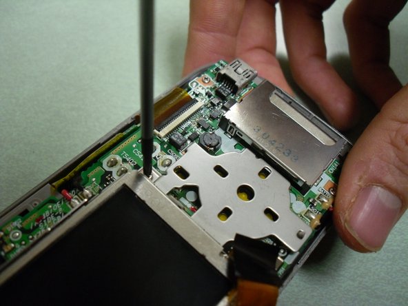
Undo the clip holding the ribbon cable that attaches the LCD screen to the motherboard.
-
-
이 단계는 번역되지 않았습니다. 번역을 도와주십시오
-
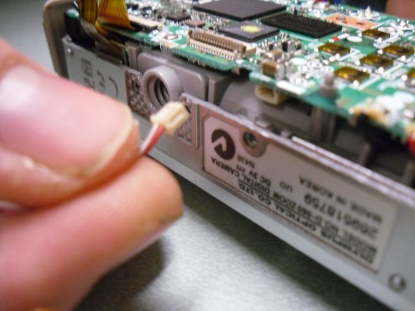
Unclip the plug attached to the red and white wires that connects the LCD screen to the motherboard.
-


팀

University of Maine, Team 1-27, Diaz Fall 2011 University of Maine, Team 1-27, Diaz Fall 2011 회원
UMAINE-DIAZ-F11S1G27
1 회원
안내서 3개 작성하였습니다