이 버전에는 잘못된 편집 사항이 있을 수 있습니다. 최신 확인된 스냅샷으로 전환하십시오.
필요한 것
-
이 단계는 번역되지 않았습니다. 번역을 도와주십시오
-
Press and slide the battery cover retainer clip to the left. Use tweezers to lift the battery cover away.
-
-
이 단계는 번역되지 않았습니다. 번역을 도와주십시오
-
Remove the single screw from the battery housing using a Phillips #00 screwdriver.
-
-
이 단계는 번역되지 않았습니다. 번역을 도와주십시오
-
To avoid disconnection of the connector line to the motherboard, use caution when pulling faceplate away from camera case.
-
-
이 단계는 번역되지 않았습니다. 번역을 도와주십시오
-
Using a Phillips #00 screwdriver, remove three screws fastened to the camera backplate edge.
-
-
-
이 단계는 번역되지 않았습니다. 번역을 도와주십시오
-
Using a Phillips #00 screwdriver, remove the two camera flash screws secured to either side of bulb housing component.
-
-
이 단계는 번역되지 않았습니다. 번역을 도와주십시오
-
Using an iFixit opening tool, pry the backplate from the camera internal housing component.
-
-
이 단계는 번역되지 않았습니다. 번역을 도와주십시오
-
Remove one screw Phillips #00 from the right side of the LCD screen camera internal housing component.
-
-
이 단계는 번역되지 않았습니다. 번역을 도와주십시오
-
To check that all screws are removed from the exterior side panel, gradually slide and lift no more than 3cm away from the camera internal component body.
-
-
이 단계는 번역되지 않았습니다. 번역을 도와주십시오
-
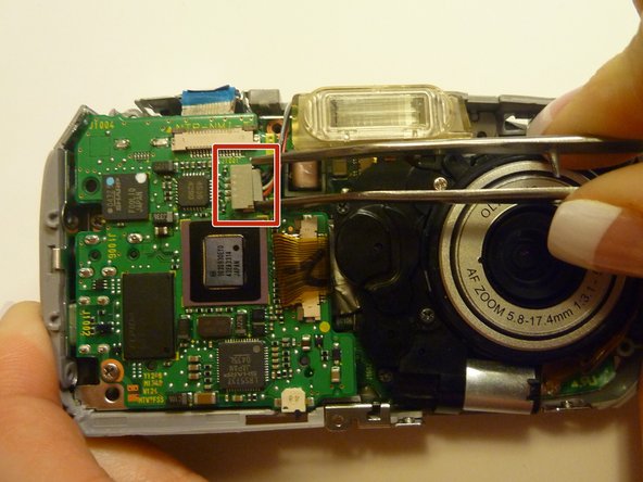
View the front of the camera internal housing component.
-
Using tweezers, detach the gray connector and blue wiring tape.
-
-
이 단계는 번역되지 않았습니다. 번역을 도와주십시오
-
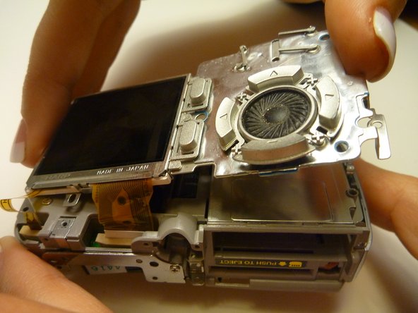
View the top of the camera internal housing component.
-
Using tweezers, gently lift the black tape exposing all connector wires.
-
-
이 단계는 번역되지 않았습니다. 번역을 도와주십시오
-
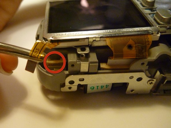
View the bottom of the camera internal housing component.
-
Use tweezers to gently wiggle, pull, and detach tape from the surface of the camera internal housing component.
-
-
이 단계는 번역되지 않았습니다. 번역을 도와주십시오
-
View the front of the camera internal housing component.
-
Using tweezers, gently lift the speaker, cautiously maneuvering the wire away from the side of the internal housing component toward the front of the camera internal housing component.
-
-
이 단계는 번역되지 않았습니다. 번역을 도와주십시오
-
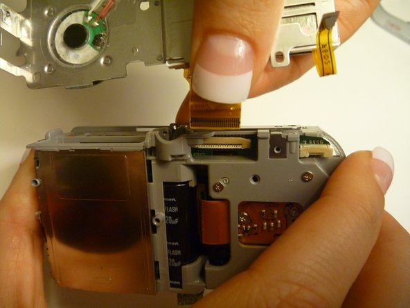
Gently lift the LCD screen away from the camera internal housing component hinging the thick yellow wiring tape attached to the camera internal housing component.
-
Use a forefinger and thumb to gently pull the thick yellow wiring tape out of the camera internal housing component.
-
-
이 단계는 번역되지 않았습니다. 번역을 도와주십시오
-
Flip the camera so you are looking at the back.
-
Looking at the back of the camera, remove the 3 screws behind the camera lens.
-
-
이 단계는 번역되지 않았습니다. 번역을 도와주십시오
-
Flip the camera so that the front lens is facing up.
-
Disconnect the lens from the logic board.
-
-
이 단계는 번역되지 않았습니다. 번역을 도와주십시오
-
Flip the camera back over so that the back of the camera is facing you, and the lens in facing away.
-
Disconnect the wire that connects the logic board to the lens assembly.
-
-
이 단계는 번역되지 않았습니다. 번역을 도와주십시오
-
Flip the camera back around so that the front is facing you.
-
Carefully lift the lens assembly out of the camera.
-


팀

Cal Poly, Team 28-23, Regan Spring 2010 Cal Poly, Team 28-23, Regan Spring 2010 회원
CPSU-REGAN-S10S28G23
4 회원들
안내서 14개 작성하였습니다