소개
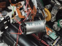
A common failure of the Pentax ZX/MZ cameras is the Mirror Motor Gear. The gear drives core functions of the camera including the shutter and mirror movement. If it fails, the shutter will no longer fire and the mirror will be stuck close in the up position.
This guide explains how to disassemble the camera to access the Mirror Motor Gear as well as how to install a new gear. A general understanding of how cameras work is recommended. Some technical soldering is also required.
필요한 것
-
-
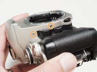
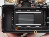
Push down on the screw to depress the spring loaded hinge and release the door.
-
-
-
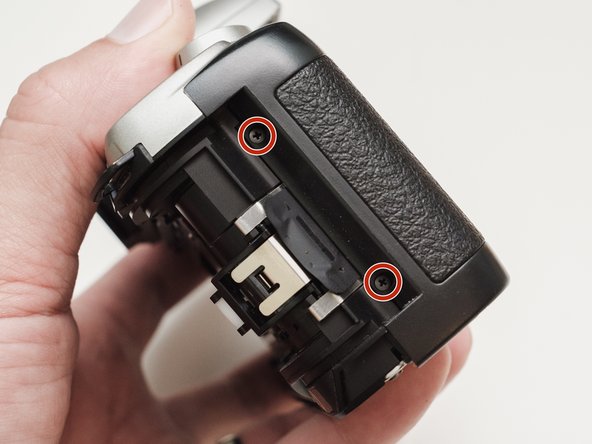
Remove three 5.3 mm #00 screws (the bottom-most screw is not always present).
-
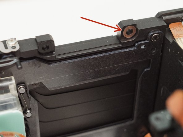
Remove one 7.3 mm #00 screw.
-
Remove the remote trigger cover.
-
-
-
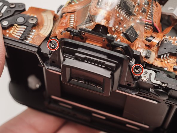
Remove two 5.3 mm #00 screws by the eyepiece.
-
Remove one 6.8 mm #00 screw in the battery compartment.
-
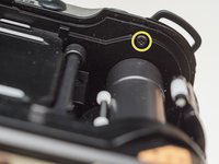
Remove one 7.0 mm #00 screw near the take up spool.
-
-
-
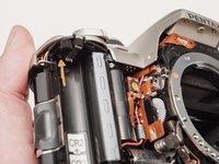
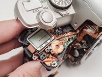
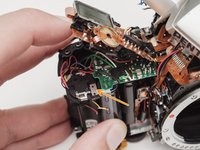
Lift the cover so it is just free of the body. It is still attached by several wires.
-
-
-
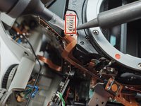
Use a 1kΩ-10kΩ resistor to discharge the capacitor. Place the resistor between the blue wire, exposed in the previous step, and ground.
-
-
-
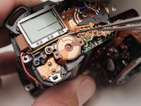
Unsolder one green wire.
-
Unsolder one blue wire.
-
Unsolder one brown wire.
-
Unsolder one black wire.
-
-
-
Unsolder one black wire.
-
Pull black wire out from its routed location.
-
Unsolder flex connector
-
-
-
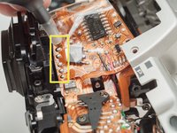
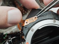
De-solder the indicated joints. Use a solder sucker on the tabbed connections.
-
Pull the black wire from the battery flex to get more slack in the connection to the top cover.
-
-
-
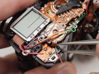
Use a solder sucker to de-solder the four posts from the flex circuit.
-
-
-
-
Unsolder film advance motor connections.
-
Unsolder sprocket counter connections.
-
Unsolder power and ground connections.
-
Unsolder panorama switch connections.
-
-
-
Gently pry up the plastic carrier under the flex circuit. It may catch slightly on the battery contact tab.
-
This metal tab is lightly held in place with lacquer and can easily come loose. Keep an eye on it.
-
-
-
Remove one 3.3mm #00 screw.
-
Remove one 3.9 #00 screw.
-
De-solder the red wire.
-
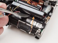
Peel off the black tape. Leave it attached to the wires.
-
-
-
Gently peel the flex circuit from the surface of the capacitor.
-
There may be additional adhesive underneath the larger capacitor.
-
Lift the two capacitors and the flash PCB out as a single unit.
-
-
-
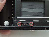
Remove two 3.4 mm #00 screws. Remove the plate holding the contacts in place.
-
Peel tape from the plate. Leave the tape attached to the flex circuit.
-
Remove the flex circuits from their retaining studs.
-
-
-
Remove one 3.3 mm #0 countersunk screw.
-
Remove one 3.9 mm #0 shoulder screw.
-
Remove four 3.3 mm #00 screws.
-
Pull a little slack through the housing on this flex cable.
-
Pop the plate off its posts, rotate slightly clockwise and pull gently through the loosened flex cable.
-
-
-
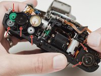
It's best to remove these parts now so they don't fall out later on in the repair.
-
-
-
De-solder the connections.
-
Lift the flex off the retaining studs.
-
-
-
Remove two 7.4 mm #0 screws.
-
Remove one 8.3 mm #0 screw.
-
Remove one 3.3 mm #00 screw. The metal bracket will be loose and should be removed as well.
-
-
-
Push the front housing block slightly up then lift the left side up and away from the housing.
-
Proceed slowly and watch for any components that are catching. The right side is still attached by a large flex cable.
-
-
-
There may be shims at the mounting points of the front housing block.
-
Note the positions and remove if loose.
-
-
-
De-solder the black wire.
-
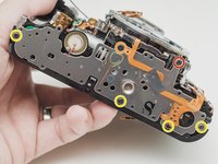
Remove four 3.7 mm #00 screws.
-
Detach the buzzer from its mounting posts. Use isopropyl alcohol to soften the lacquer if necessary.
-
-
-
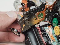
Grab the motor and gently wiggle the plate loose.
-
If it feels stuck, move the sliding plate down, towards the bottom of the camera
-
-
-
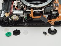
Pull off the old gear.
-
Press the new gear on until about 1 mm of the shaft extends past the end.
-
-
-
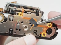
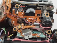
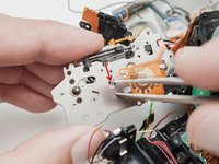
The green and yellow gears can sometimes slip off their posts while working with the motor.
-
Check that the alignment holes are properly synced before installing the mirror motor assembly.
-
Aperture set lever spring. Note this part for installation of the mirror motor assembly.
-
-
-
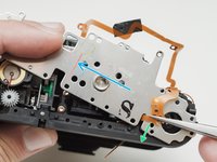
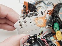
Disengage latch so the slide bar can move freely.
-
Move the slide bar about half way down its total travel.
-
Let the latch snap back into place so the slide bar is held in the new position.
-
-
-
Install the mirror motor.
-
Place the left side first. Then swing the right side in, coming up and under the spring loaded lens release.
-
-
-
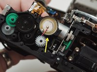
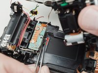
Rotate the grey gear downward until the mirror is in the charged/down position.
-
-
-
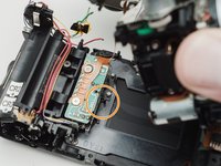
Push the shutter charge lever upward. You should see the shutter blades move as you do this.
-
The second picture shows the shutter in the charged position. It may already be in this position and not need charging.
-
-
-
Gently place the front assembly block. Work it into place until the back of the block is flush to the back of camera.
-
Proceed with the rest of the re-assembly, following the guide in reverse.
-


To reassemble your device, follow these instructions in reverse order.
To reassemble your device, follow these instructions in reverse order.
다른 7명이 해당 안내서를 완성하였습니다.
댓글 4개
Grazie è semplicemente perfetto
I went though this guide it is pretty good and easy. Thanks for your work.
Although I ended up with a camera always in dof mode. When I try to turn it off it buzzes, but the finder stays dark in smaller apertures. Any tips on that?
It's hard to say precisely what the issue is but my guess is something around the aperture set lever. Unfortunately, I think you have to take it all apart and put it back together. Sometimes you just miss something. I would double check steps 32 and 33 and make sure those are followed during reassembly. You can also check out this video for a more in depth description of how the aperture mechanism is supposed to work. It might point you towards a more specific area.