이 버전에는 잘못된 편집 사항이 있을 수 있습니다. 최신 확인된 스냅샷으로 전환하십시오.
필요한 것
-
이 단계는 번역되지 않았습니다. 번역을 도와주십시오
-
Use a coin or a spudger to turn the battery locking screw 90 degrees clockwise.
-
Lift the battery out of the computer.
-
-
이 단계는 번역되지 않았습니다. 번역을 도와주십시오
-
Remove the four Phillips screws from the memory door.
-
Slide the memory door away from the memory compartment.
-
-
이 단계는 번역되지 않았습니다. 번역을 도와주십시오
-
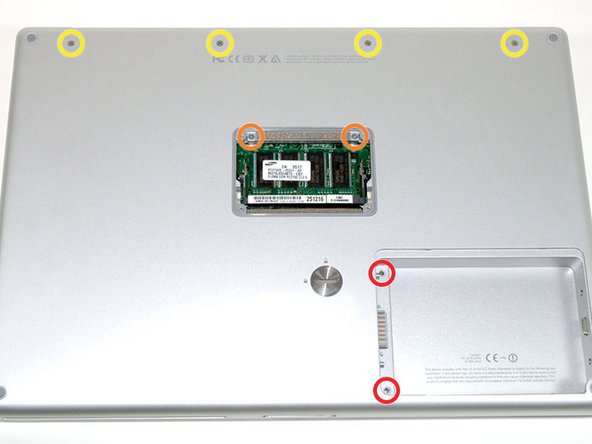
Remove the following 8 screws:
-
Two 3 mm Phillips in the battery compartment, on either side of the battery contacts.
-
Two 12 mm Phillips on either side of the memory compartment.
-
Four 16 mm Phillips along the hinge.
-
-
이 단계는 번역되지 않았습니다. 번역을 도와주십시오
-
Rotate the computer 90 degrees clockwise, so that the power receptacle faces you.
-
Remove the three 3 mm Phillips screws.
-
-
이 단계는 번역되지 않았습니다. 번역을 도와주십시오
-
Turn the computer 90 degrees clockwise so that the hinge faces you.
-
Remove the bottom 5 mm Phillips screw on either side of the hinge (two total).
-
-
이 단계는 번역되지 않았습니다. 번역을 도와주십시오
-
Rotate the computer 90 degrees clockwise, so that the ports face you.
-
Remove the three 3 mm Phillips screws.
-
-
이 단계는 번역되지 않았습니다. 번역을 도와주십시오
-
Turn the computer over and open the display.
-
Remove the two 1.5 mm hex screws in either corner, next to the display (a T6 Torx driver will work, but repeated use will strip the screws).
-
-
이 단계는 번역되지 않았습니다. 번역을 도와주십시오
-
Grasp the back corners of the upper case and pull up. Do not pull the upper case off yet; you still need to disconnect the keyboard and trackpad cable.
-
Lift the back of the case up and work your fingers along the sides, freeing the case as you go. Once you have freed the sides, you may need to rock the case up and down to free the front of the upper case.
-
-
-
이 단계는 번역되지 않았습니다. 번역을 도와주십시오
-
Rotate the upper case up and toward the screen, so that the upper case rests against it.
-
-
이 단계는 번역되지 않았습니다. 번역을 도와주십시오
-
Remove the orange tape securing the trackpad ribbon to the logic board.
-
Disconnect the trackpad ribbon from the logic board.
-
Remove the upper case from the computer.
-
-
이 단계는 번역되지 않았습니다. 번역을 도와주십시오
-
Remove the 9.5 mm silver Phillips screw from the top of the right ambient light sensor board.
-
Remove the small 3 mm black Phillips screw from the bottom of the board.
-
-
이 단계는 번역되지 않았습니다. 번역을 도와주십시오
-
Lift the right ambient light sensor board Straight up from the Logic Board.
-
-
이 단계는 번역되지 않았습니다. 번역을 도와주십시오
-
Remove the two black Phillips screws from the right speaker.
-
Lift the speaker away from the logic board and place it aside
-
-
이 단계는 번역되지 않았습니다. 번역을 도와주십시오
-
Use your fingernail to flip up the black plastic flap locking the modem cable in place.
-
Slide the modem cable from its connector.
-
-
이 단계는 번역되지 않았습니다. 번역을 도와주십시오
-
Remove the following 8 Phillips screws from the logic board:
-
Three 6.5 mm in the upper left corner.
-
Five 4.5 mm around the edges.
-
-
이 단계는 번역되지 않았습니다. 번역을 도와주십시오
-
Use a spudger to gently (very gently) pry up the left side of the logic board.
-
-
이 단계는 번역되지 않았습니다. 번역을 도와주십시오
-
Disconnect the battery cable from the front, left corner of the logic board.
-
-
이 단계는 번역되지 않았습니다. 번역을 도와주십시오
-
Grasp the logic board at the left edge with one hand and at the thinnest section with the other hand. Lift the left edge of the board up to approximately a 30 degree angle (if you don't have your protractor handy, just lift until the DVI port clears the right hinge).
-
Once the logic board clears the ports, slide it out to the left.
-
-
이 단계는 번역되지 않았습니다. 번역을 도와주십시오
-
To properly reassemble your PowerBook, you'll have to clean off and replace the old thermal compound. Use our Applying Thermal Paste Guide to prepare the processor and heat sink surfaces.
-
-
이 단계는 번역되지 않았습니다. 번역을 도와주십시오
-
Use a firm plastic edge to scrape the thermal material off the processor.
-


다른 13명이 해당 안내서를 완성하였습니다.
첨부 문서

댓글 2개
I replaced my logic board using the wrong guide (Model A1138) but luckily there was only a few differences between guides
Well, that's funny!
They are basically the same.