소개
Into brain surgery? This guide will show you how to remove your logic board.
필요한 것
-
-
Use a coin to turn the battery locking screw 90 degrees clockwise.
-
Lift the battery out of the computer.
-
-
-
Remove the following 10 screws:
-
Two 3 mm Phillips in the battery compartment, on either side of the battery contacts.
-
Four 3 mm Phillips around the memory compartment.
-
Four 16 mm Phillips along the hinge.
-
-
-
Remove the memory compartment cover.
-
Remove the two 12 mm Phillips screws on the Aluminum bracket at the top of the memory compartment.
I have an Aluminum PowerBook G4 1.67Ghz since 2006.
3/4 (from bottom to top) of the LCD becomes either black or is jumbled each time I turn on the MAC or move the screen. I need to press the LCD at several locations in order for this problem to go.... any advice ?
-
-
-
Rotate the computer 90 degrees clockwise so the ports face you.
-
Remove the three 3 mm Phillips screws along the edge of the lower case.
-
When replacing these screws, you must install them in the correct order. Begin by installing the screw closest to the display hinge, then work your way toward the front of the computer. Also, be careful not to put the screws in the two holes on either side of the video out port.
-
-
-
-
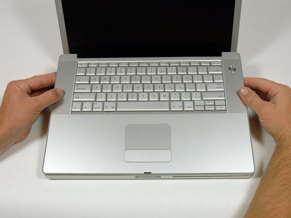
Rotate the upper case up and toward the screen, so that the upper case rests against it.
First of all, awesome guide. I am using it in July 2015, and there is no way I could have successfully navigate the typical Apple laptop Rubik's cube of Powerbook maintenance.
Second, there is a REAL trick to removing the upper case here, and it involves knowing what those stupid internal metal catches look like so you can free them without folding your aluminum case into a pretzel.
-
-
-
Remove the amber tape securing the trackpad ribbon to the logic board.
-
Disconnect the trackpad ribbon from the logic board by pulling up on the connector.
-
Remove the upper case from the computer.
-
-
-
Remove the 12 mm Phillips screw holding the right speaker assembly to the lower case.
-
-
-
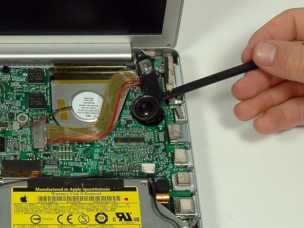
Lift the left side of the logic board and disconnect the modem cable from the underside of the logic board. A spudger is useful for freeing the connector from its adhesive.
Ben Ruiz is right. Due to its short length, I found no way to sneak this cable under the logic board and attach it. Its not hard at all to remove the PC cage first ( which also mean removing the left speaker housing), then you can plug the cable into the board before you maneuver the board into place, and then plug the cable to the socket exposed by having removed the PC cage. Then replace the PC cage.
The cable is very short and it is very difficult to reach under the board to attach it when reassembling the computer. It helps to remove the large connector from the modem itself (visible in Step 24, marked Foxcomm and OK) to be able to reach under the board. Then attach the modem-side of the cable.
-
-
-
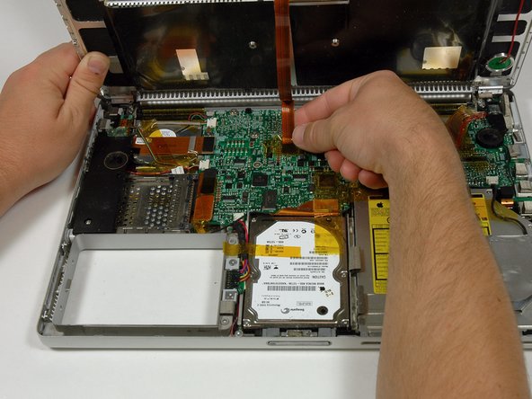
Very gently lift up the left side of the logic board.
-
Lift the left edge of the board up to approximately a 30 degree angle (if you don't have your protractor handy, just lift until the DVI port clears the right hinge).
-
Once the logic board clears the ports, slide it out to the left.
It is much, MUCH easier if you take out the screen before messing around with the logic board. On the way back is also easier if you put the logic board before the screen.
-


To reassemble your device, follow these instructions in reverse order.
To reassemble your device, follow these instructions in reverse order.
다른 15명이 해당 안내서를 완성하였습니다.
