필요한 것
-
-
First, run cosmetic inspection of the logic board. The logic board bears no deformation or water damage issue.
-
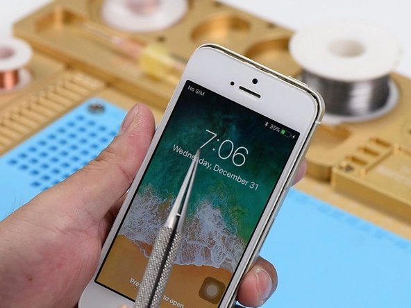
Next, let's assemble the phone and test. Get the logic board and display assembly installed. Connect the battery and press the power button. Battery percentage in the upper-right corner displays as 10%.
-
Plug in the charging cable. The lightning bolt shows up on the screen. After charging for 10 minutes, battery percentage in the upper-right corner still displays as 10%, which indicates that the charging circuit has malfunctioned.
-
-
-
-
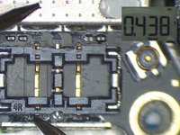
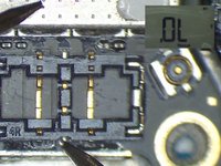
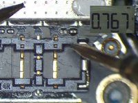
Disconnect the charging cable and remove the display assembly. Run diode mode measurement of J2400. The measured value of Pin 5 is 436, which is normal. The measured value of Pin 2 is OL, which is abnormal. Normal value should be around 600. Judging by this, Pin 2 relevant circuit has been open-circuited.
-
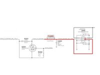
Pin 2 of J2400 is the battery percentage detect signal of the phone, which connects to Pin 3 of Q2301 by way of FL2400. The rail extends to Pin F2 of U2300 by way of Pin 1 of Q2301 and then R2303. Also when we are measuring, we find that FL2400 is missing.
-
-
-
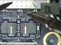
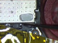
Since FL2400 is a coupled inductor, we can fix the problem by connecting the two pins with Solder Paste. Now, let's take out the logic board. Stick High Temperature Protective Tape on J2400.
-
Apply low-temperature Solder Paste to the bonding pad of FL2400. Heat with Hot Air Gun at 240℃, air flow 2. Then connect the two pins with melted Solder Paste. Wait for the logic board to cool for 5 minutes. Clean with PCB Cleaner afterwards.
-


To reassemble your device, follow these instructions in reverse order.
To reassemble your device, follow these instructions in reverse order.
다른 한 분이 해당 안내서를 완성하였습니다.
