이 버전에는 잘못된 편집 사항이 있을 수 있습니다. 최신 확인된 스냅샷으로 전환하십시오.
필요한 것
-
이 단계는 번역되지 않았습니다. 번역을 도와주십시오
-
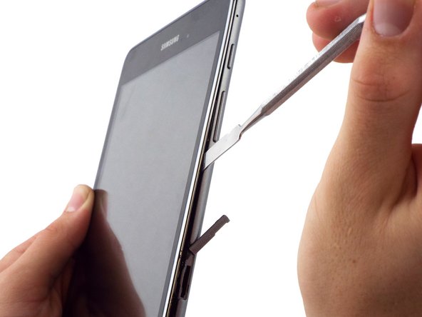
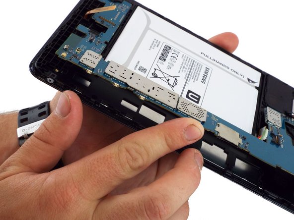
At the top portion of the memory card slot, use the small metal spudger to create separation between the back cover and the rest of the device.
-
-
이 단계는 번역되지 않았습니다. 번역을 도와주십시오
-
Use the intermediate metal spudger in place of the small metal spudger to remove the back cover. This is done by sliding the intermediate metal spudger around the perimeter of the device, beginning at the top portion of the memory card slot.
-
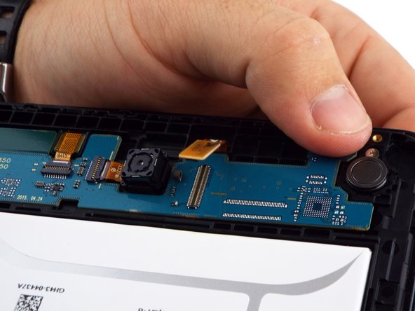
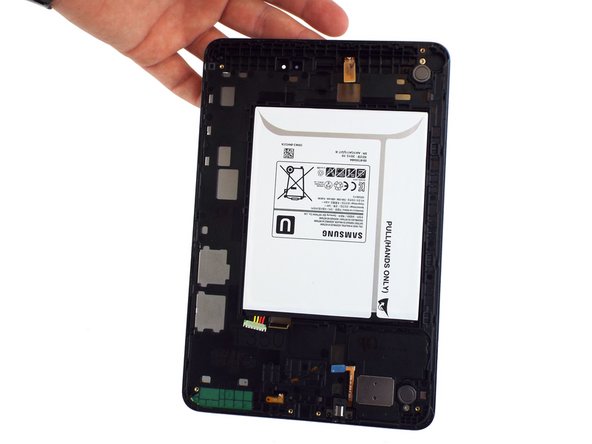
The second picture shows the internal portion of the device once the back cover is removed.
-
-
이 단계는 번역되지 않았습니다. 번역을 도와주십시오
-
Disconnect the electrical connector from the motherboard using the bent precision tweezers.
-
-
이 단계는 번역되지 않았습니다. 번역을 도와주십시오
-
Use the flat end of the plastic spudger to pry the battery apart from the rest of the device.
-
Once the back cover and battery are removed, the device should look like as illustrated in the second picture.
-
-
-
이 단계는 번역되지 않았습니다. 번역을 도와주십시오
-
Use a spudger to lift up and release the press-fit display cable connector from the motherboard.
-
-
이 단계는 번역되지 않았습니다. 번역을 도와주십시오
-
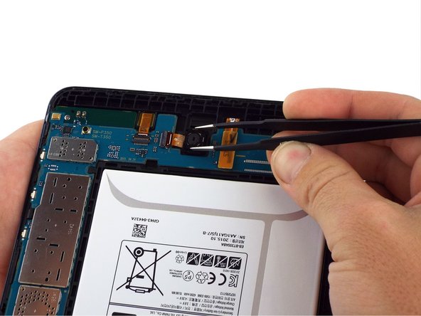
Use a spudger to lift up and release the ZIF connector; gently pull the rear facing camera ribbon cable free.
-
Use a pair of tweezers to gently secure the camera and lift it out of the frame.
-
-
이 단계는 번역되지 않았습니다. 번역을 도와주십시오
-
Use a spudger to flip the front-facing camera ZIF connector up; gently pull the ribbon cable free.
-
Use tweezers to gently remove the front facing camera from the frame.
-
-
이 단계는 번역되지 않았습니다. 번역을 도와주십시오
-
Use the flat end of a spudger to lift up and disconnect the LCD screen press-fit connector.
-
-
이 단계는 번역되지 않았습니다. 번역을 도와주십시오
-
Use the flat end of a spudger to lift up and disconnect the 3.5mm headset jack press-fit connector.
-
-
이 단계는 번역되지 않았습니다. 번역을 도와주십시오
-
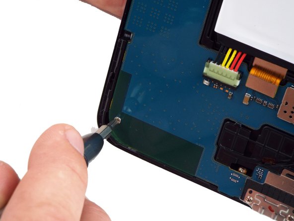
Use a PH000 screwdriver to remove the two 3 mm screws that connect the USB port shield to the midframe.
-
-
이 단계는 번역되지 않았습니다. 번역을 도와주십시오
-
Use a PH000 screwdriver to remove the two 3 mm screws on the left side of the motherboard.
-
-
이 단계는 번역되지 않았습니다. 번역을 도와주십시오
-
Lift the motherboard free from the power and volume button side.
-
You may use a spudger to assist in gently lifting the motherboard up from the button side.
-
A small plastic bracket secures the motherboard to the frame; lift the motherboard from the power and volume button side first, and slide away from the bracket.
-


다른 13명이 해당 안내서를 완성하였습니다.


댓글 3개
Where is the rest of this guide? Just stops after removing motherboard :[
It appears that it is intended to remove all parts from the case (battery and motherboard) and install them in a new body with a good screen attached.
Ben D -
After removing the motherboard, I continued with disassembly by following the iFixit guide for the Digitizer removal.
( Samsung Galaxy Tab A Digitizer Replacement )
After removing the glass/digitizer, I was able to remove the LCD relatively easy by pushing it through the gaps on the back end of the frame. It appeared to not have any adhesive holding it in place. I was replacing the LCD and the digitizer in my case so I was I bit more careless with the removal of those components. I did place a bit of adhesive on the new LCD replacement and everything fit back snuggly.