이 버전에는 잘못된 편집 사항이 있을 수 있습니다. 최신 확인된 스냅샷으로 전환하십시오.
필요한 것
-
이 단계는 번역되지 않았습니다. 번역을 도와주십시오
-
Remove the 12mm screws with the Philips #2 screwdriver which keep the plastic panels in place.
-
Don't forget, there are two more 12mm screws on the other side as well.
-
-
이 단계는 번역되지 않았습니다. 번역을 도와주십시오
-
First, remove the three 12mm black screws holding the top panel on (Phillips #2).
-
Then, remove the two 12mm black screws - one on each side of the back of the device - holding the top panel on.
-
Lastly, remove the three 12mm black screws on each side of device.
-
-
이 단계는 번역되지 않았습니다. 번역을 도와주십시오
-
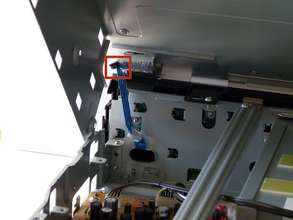
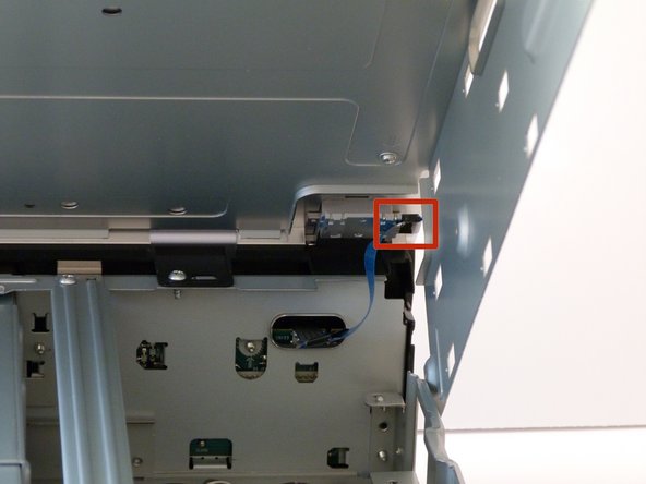
After gently disconnecting the two ribbon cables (you can just pull them out with your hand), take the top off and set it to the side.
-
-
-
이 단계는 번역되지 않았습니다. 번역을 도와주십시오
-
After the top is off, you'll see that there are two metal bars that go across the top of the device.
-
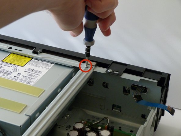
Remove each bar by unscrewing the two 10mm silver screws on each end.
-
-
이 단계는 번역되지 않았습니다. 번역을 도와주십시오
-
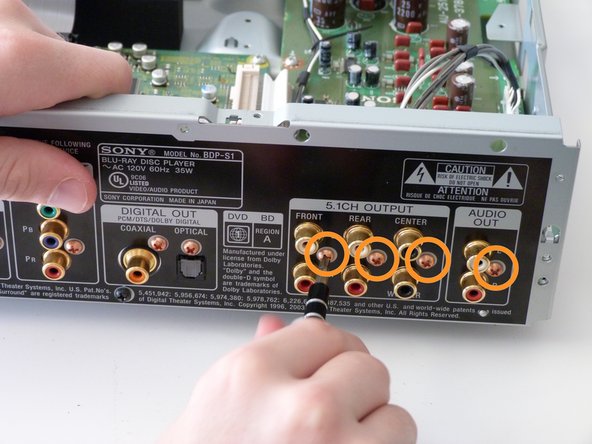
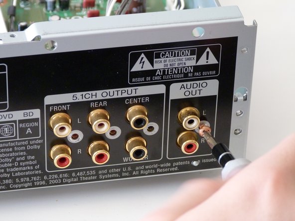
These are the RC sockets. They are the audio output that sends a signal set of speakers.
-
Unscrew the frame to access the circuit board.
-
Remove the four screws circled in the figure using a Phillips #2 Screwdriver.
-
-
이 단계는 번역되지 않았습니다. 번역을 도와주십시오
-
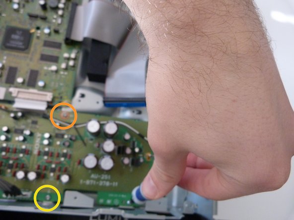
White arrows point to the screws that are required for removal.
-
Remove the three screws circled in orange with a Phillips #2 Screwdriver.
-
Remove the three screws opposite to the orange screws with a Phillips #2 Screwdriver.
-
-
이 단계는 번역되지 않았습니다. 번역을 도와주십시오
-
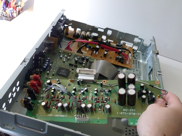
Remove the cable ribbon that is attached to the motherboard.
-
And voila! You have successfully taken out the circuit board.
-
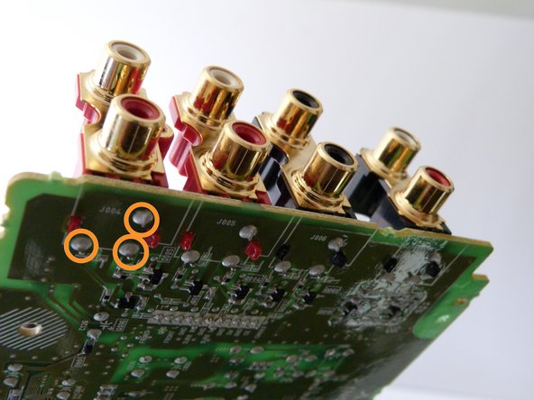
And here we see the solder that keeps the RC components strapped into the board. In order to get them off and put them back on, you'll need a soldering iron, wick, and solder itself.
-
If you don't know how to solder properly, there are plenty of helpful guides online, such as this one. Make sure to remove the solder all the way before removing the RC jacks, otherwise you could hurt the board.
-
Now you just have to take off the RC components, place the news ones in, and solder them into the board (again using a soldering guide if you need to).
-
Good work! Now celebrate by listening to your favorite movie!
-


첨부 문서
팀

Cal Poly, Team 12-3, Green Winter 2015 Cal Poly, Team 12-3, Green Winter 2015 회원
CPSU-GREEN-W15S12G3
4 회원들
안내서 6개 작성하였습니다