이 버전에는 잘못된 편집 사항이 있을 수 있습니다. 최신 확인된 스냅샷으로 전환하십시오.
필요한 것
-
이 단계는 번역되지 않았습니다. 번역을 도와주십시오
-
Start using the iFixit Opening Tool in the SD/SIM area to release the clips holding the back panel on.
-
-
이 단계는 번역되지 않았습니다. 번역을 도와주십시오
-
Follow along the edge of the device to undo all of the retaining clips.
-
-
이 단계는 번역되지 않았습니다. 번역을 도와주십시오
-
Once all the clips are undone, the back panel should come off with little effort.
-
-
이 단계는 번역되지 않았습니다. 번역을 도와주십시오
-
Remove the bottom piece of tape securing the battery making sure you are not peeling up anything else in the process.
-
-
이 단계는 번역되지 않았습니다. 번역을 도와주십시오
-
Once you have a hold on the tape, carefully remove it making sure you aren’t damaging the battery in the process.
-
-
이 단계는 번역되지 않았습니다. 번역을 도와주십시오
-
Unplug the battery power connector by sliding the white plastic plug down away from the board.
-
-
-
이 단계는 번역되지 않았습니다. 번역을 도와주십시오
-
The battery should be free to come out of the device. Make sure not to bend or damage the battery.
-
-
이 단계는 번역되지 않았습니다. 번역을 도와주십시오
-
Remove the 4 M1.5 screws holding in the labeled auxiliary LTE/GPS module.
-
The module should come up with a little resistance.
-
-
이 단계는 번역되지 않았습니다. 번역을 도와주십시오
-
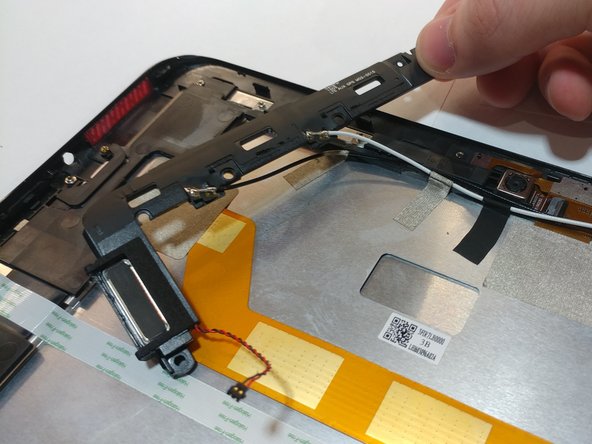
Use a pair of tweezers to lift up the front camera off its locating post.
-
-
이 단계는 번역되지 않았습니다. 번역을 도와주십시오
-
Remove the non-conductive tape covering the camera ribbon cable.
-
You may need to remove the white antenna cable to remove the tape.
-
-
이 단계는 번역되지 않았습니다. 번역을 도와주십시오
-
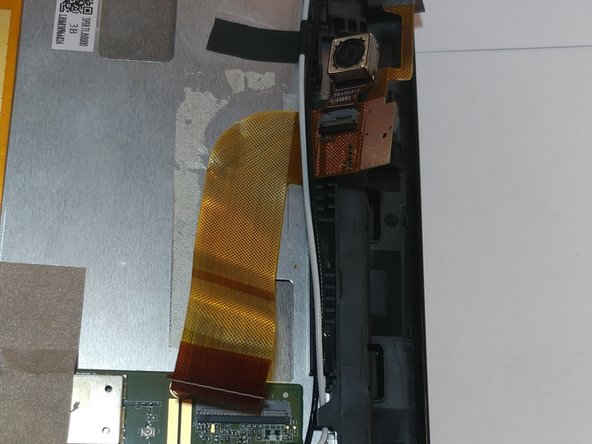
Peel up the ribbon cable carefully as it is glued to the device.
-
After having peeled up the cable, the cameras should be free to come out of the device.
-
-
이 단계는 번역되지 않았습니다. 번역을 도와주십시오
-
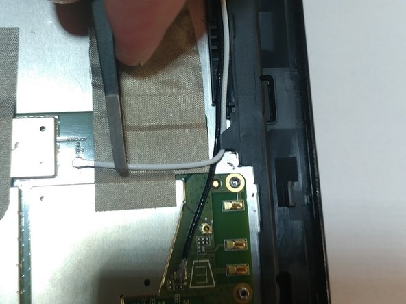
Use tweezers to pry/disconnect both the black and white antenna cables from the top of the motherboard.
-
-
이 단계는 번역되지 않았습니다. 번역을 도와주십시오
-
Once all screws are removed, the motherboard should easily come off the device without any resistance.
-


다른 한 분이 해당 안내서를 완성하였습니다.
팀

Oregon Institute of Technology, Team S2-G10, Lancaster Spring 2019 Oregon Institute of Technology, Team S2-G10, Lancaster Spring 2019 회원
OIT-LANCASTER-S19S2G10
4 회원들
안내서 7개 작성하였습니다