이 버전에는 잘못된 편집 사항이 있을 수 있습니다. 최신 확인된 스냅샷으로 전환하십시오.
필요한 것
-
이 단계는 번역되지 않았습니다. 번역을 도와주십시오
-
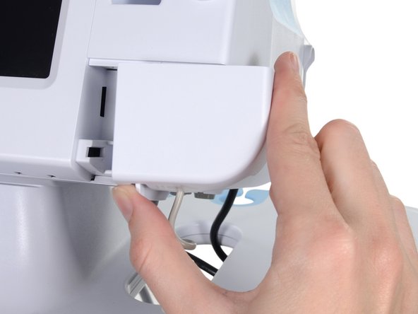
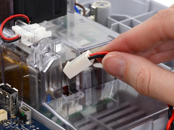
Place your thumb and forefinger on the blood pressure (NIBP) hose connector. Squeeze the side tabs until the connector releases.
-
Pull the connector away from the connector port.
-
-
이 단계는 번역되지 않았습니다. 번역을 도와주십시오
-
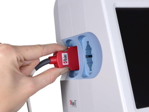
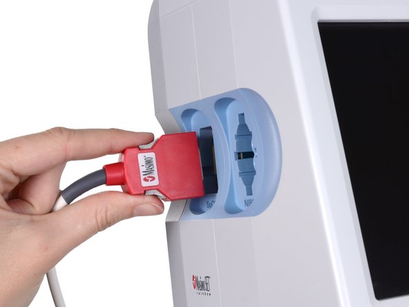
Place your thumb and forefinger on the Pulse oximetry (SpO2 or combined SpO2/SpHb) cable connector. Squeeze the side tabs until the connector releases.
-
Pull the connector away from the connector port.
-
-
이 단계는 번역되지 않았습니다. 번역을 도와주십시오
-
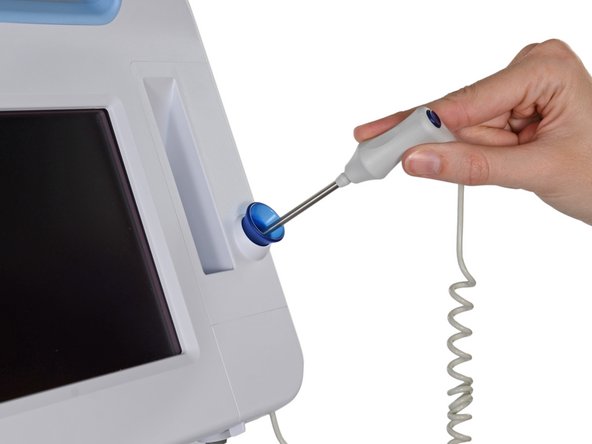
Grasp the temperature probe and pull it up to remove it from the monitor.
-
-
이 단계는 번역되지 않았습니다. 번역을 도와주십시오
-
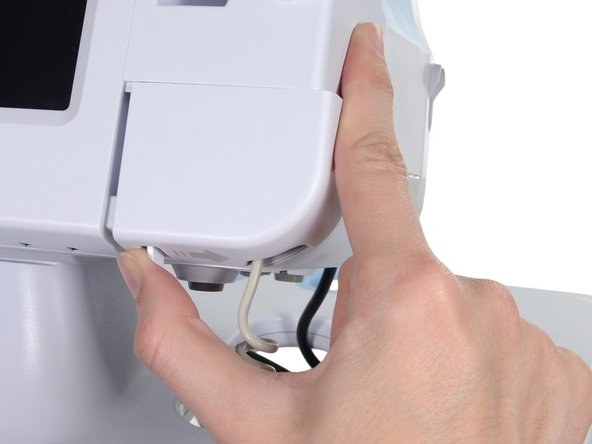
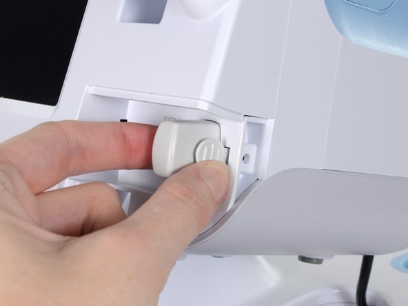
Remove the cover of the temperature module by pressing the tab and sliding the cover to the right.
-
-
이 단계는 번역되지 않았습니다. 번역을 도와주십시오
-
Depress the spring tab on the temperature probe cable connector and withdraw it from the probe port.
-
-
이 단계는 번역되지 않았습니다. 번역을 도와주십시오
-
Remove the flathead screw on the USB networking door.
-
Loosen the captive Phillips #2 screw securing the monitor to the stand.
-
-
이 단계는 번역되지 않았습니다. 번역을 도와주십시오
-
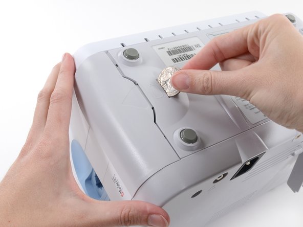
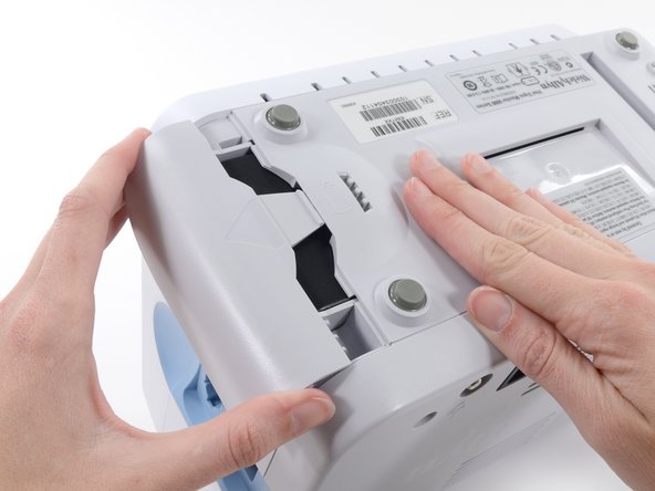
Insert a coin into the slot and push to open.
-
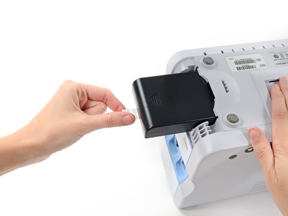
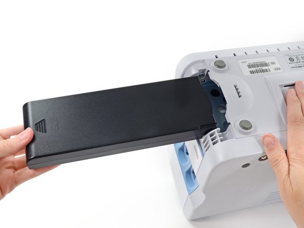
Remove the battery cover.
-
-
이 단계는 번역되지 않았습니다. 번역을 도와주십시오
-
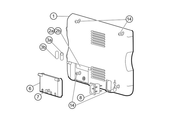
Remove the four Phillips #2 screws (labeled 14 in the service manual) from the rear housing.
-
-
이 단계는 번역되지 않았습니다. 번역을 도와주십시오
-
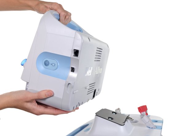
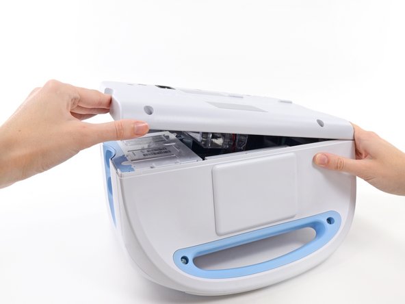
With the handle/alert bar facing you, begin to lift the rear housing from the left side, holding the right side securely.
-
-
이 단계는 번역되지 않았습니다. 번역을 도와주십시오
-
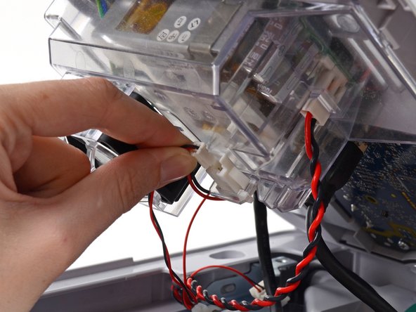
Disconnect the fan cable (labeled connector A in the service manual) from its socket in the power supply.
-
-
이 단계는 번역되지 않았습니다. 번역을 도와주십시오
-
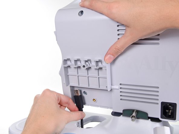
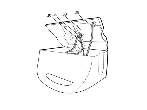
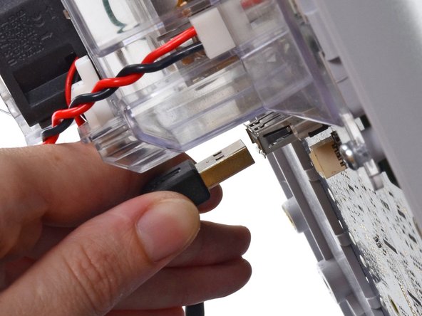
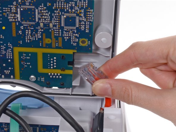
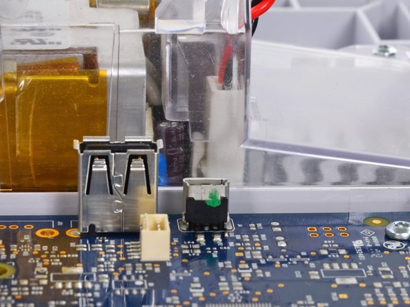
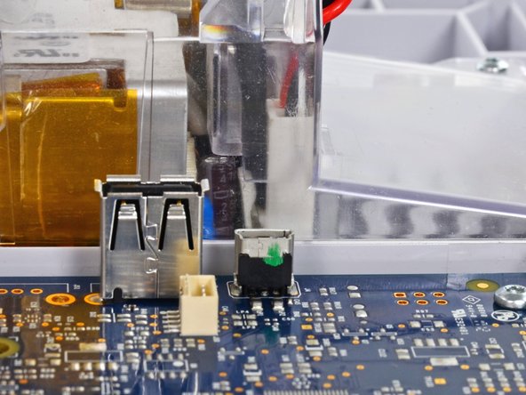
Unplug the small USB connector from its socket (labeled J4 in the service manual).
-
-
이 단계는 번역되지 않았습니다. 번역을 도와주십시오
-
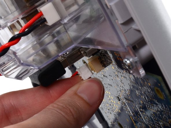
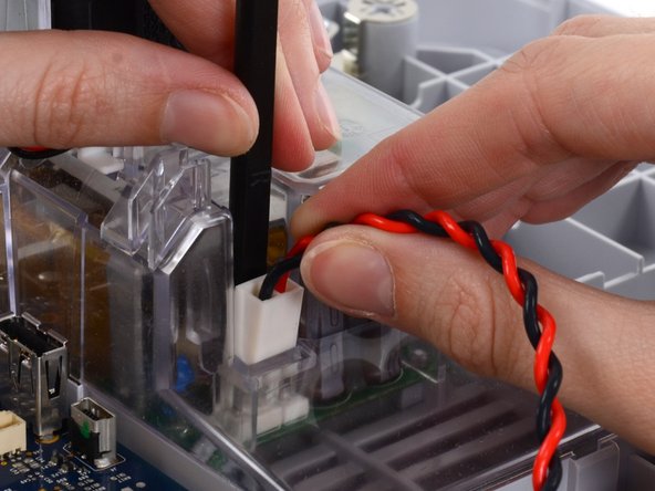
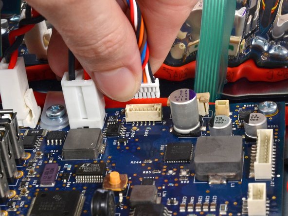
Disconnect the communications power cable from its socket (labeled J50 in the service manual).
-
-
이 단계는 번역되지 않았습니다. 번역을 도와주십시오
-
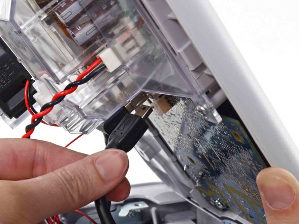
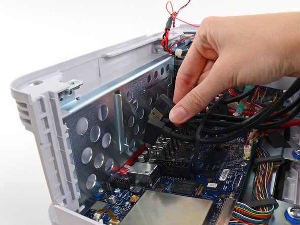
Unplug the large USB connector from its socket (labeled J8 in the service manual).
-
-
이 단계는 번역되지 않았습니다. 번역을 도와주십시오
-
Press the tab on the ethernet cable and unplug it from its socket (labeled J9 in the service manual).
-
-
이 단계는 번역되지 않았습니다. 번역을 도와주십시오
-
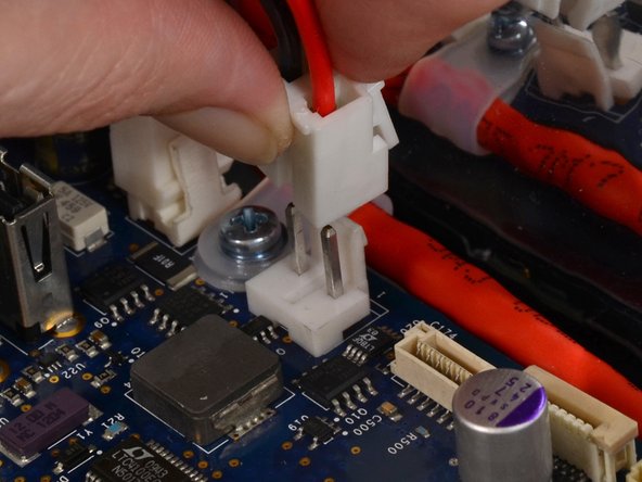
The power supply cable is secured by an interlocking connector that must be held open to unplug the connector.
-
-
이 단계는 번역되지 않았습니다. 번역을 도와주십시오
-
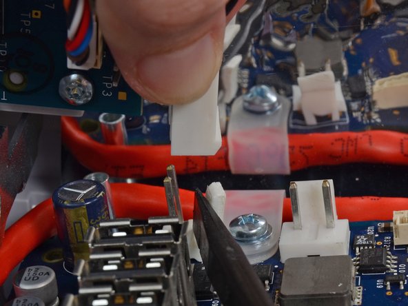
Grasp the power supply cable firmly and lift both it and the spudger from the channel in the power supply housing to unplug the connector.
-
-
이 단계는 번역되지 않았습니다. 번역을 도와주십시오
-
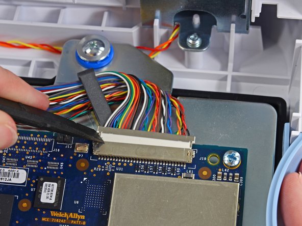
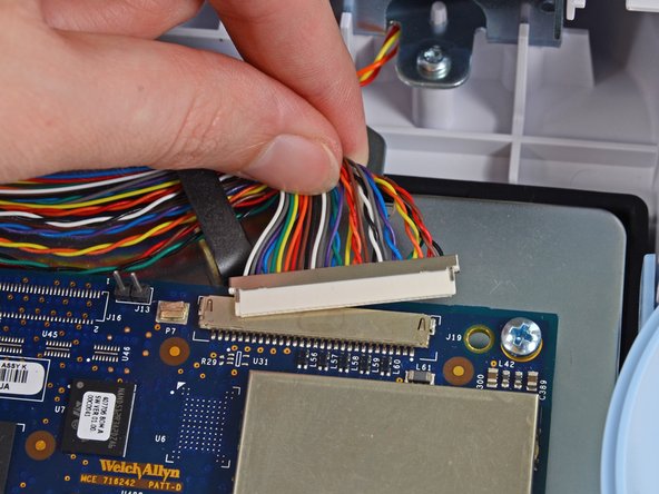
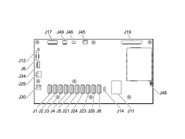
Use the flat end of a spudger to "walk" the LCD cable connector (labeled J19 in the service manual) out of its socket.
-
Press first on one side of the connector, then the other to push it free. Be sure to press the connector itself, not the socket on the motherboard.
-
Pull the cable straight out of its socket.
-
-
이 단계는 번역되지 않았습니다. 번역을 도와주십시오
-
Pinch the fan cable connector (labeled J45 in the service manual) and pull straight up to remove it from its socket.
-
-
이 단계는 번역되지 않았습니다. 번역을 도와주십시오
-
Pull the light bar cable connector (labeled J46 in the service manual) straight up out of its socket.
-
-
이 단계는 번역되지 않았습니다. 번역을 도와주십시오
-
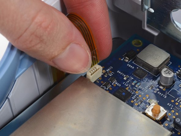
Remove the communications board cable connector from its socket (labeled J49 in the service manual).
-
-
이 단계는 번역되지 않았습니다. 번역을 도와주십시오
-
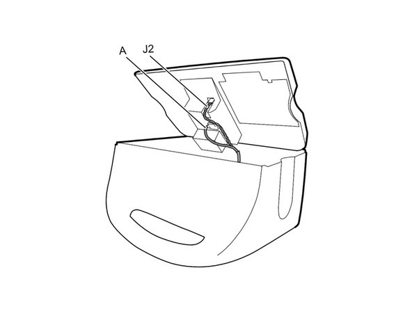
Carefully remove the speaker cable connector (labeled J12 in the service manual) from the motherboard.
-
-
이 단계는 번역되지 않았습니다. 번역을 도와주십시오
-
Lift the ZIF collar securing the power button cable (labeled J6 in the service manual) with the flat end of a spudger to loosen its grip.
-
Pull the power button cable straight up from its socket.
-
-
이 단계는 번역되지 않았습니다. 번역을 도와주십시오
-
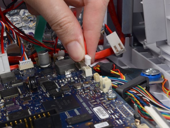
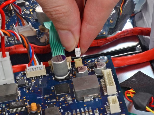
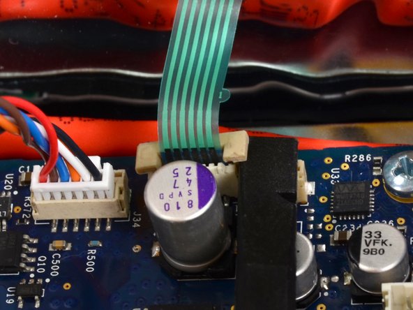
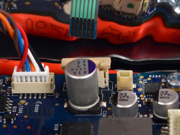
Remove the smart-battery cable connector from its socket (labeled J34 in the service manual).
-
-
이 단계는 번역되지 않았습니다. 번역을 도와주십시오
-
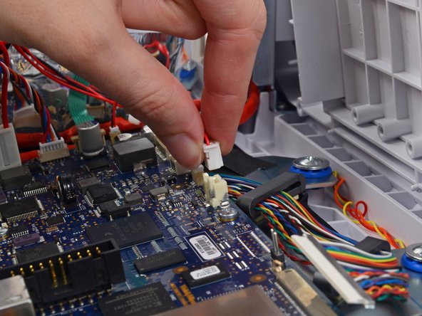
Pinch the battery power connector and lift straight up to unclip it from its socket on the motherboard (labeled J29 in the service manual).
-
-
이 단계는 번역되지 않았습니다. 번역을 도와주십시오
-
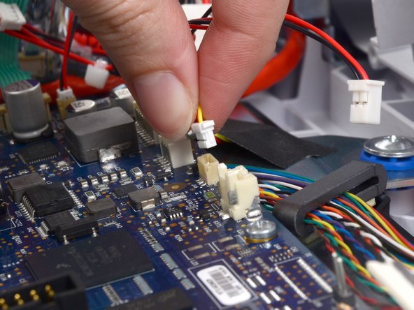
Use the flat end of a spudger to separate the battery supply cable connector bracket from the socket (labeled J30 in the service manual).
-
Pull the battery supply cable connector straight up from the board.
-
-
이 단계는 번역되지 않았습니다. 번역을 도와주십시오
-
Carefully pull the LCD flex cable straight up from its socket in the motherboard (labeled J48 in the service manual).
-
-
이 단계는 번역되지 않았습니다. 번역을 도와주십시오
-
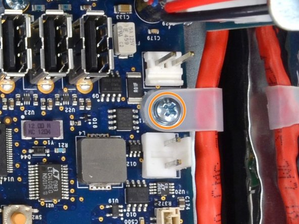
Remove the eight Phillips #1 screws from the motherboard.
-
The screw securing the ethernet cable bracket has a washer between it and the bracket. Take care not to lose it.
-
-
이 단계는 번역되지 않았습니다. 번역을 도와주십시오
-
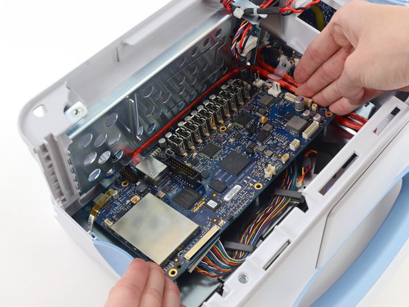
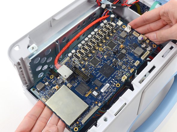
Lift the motherboard from the light-bar side and pull it toward the edge of the case to free the ethernet cable connector from under the case.
-
Lift the motherboard out of the case to gain access to the ethernet cable connector.
-
-
이 단계는 번역되지 않았습니다. 번역을 도와주십시오
-
Remove the ethernet cable connector (labeled J11 in the service manual) from the mother board.
-


다른 3명이 해당 안내서를 완성하였습니다.

