주요 콘텐츠로 건너뛰기

이 버전에는 잘못된 편집 사항이 있을 수 있습니다. 최신 확인된 스냅샷으로 전환하십시오.

단지 전제 조건
이 안내서는 다른 가이드의 선행 작업으로 사용하기 위한 것입니다. 그 자체로는 불완전합니다.

필요한 것

  1. 이 단계는 번역되지 않았습니다. 번역을 도와주십시오

    : 1 단계, 이미지 1/3 : 1 단계, 이미지 2/3 : 1 단계, 이미지 3/3
    • Disconnect and remove the SATA data and power cables from the logic board.

  2. 이 단계는 번역되지 않았습니다. 번역을 도와주십시오

    : 2 단계, 이미지 1/1
    • Remove the four 12 mm T10 shoulder screws from the spring plate behind the CPU.

  3. 이 단계는 번역되지 않았습니다. 번역을 도와주십시오

    : 3 단계, 이미지 1/1
    • Remove the spring plate from behind the CPU heat sink.

  4. 이 단계는 번역되지 않았습니다. 번역을 도와주십시오

    : 4 단계, 이미지 1/1
    • Lift and remove the backing plate from behind the CPU heat sink.

    • The backing plate has two posts that fit into alignment holes in the logic board and heat sink.

  5. 이 단계는 번역되지 않았습니다. 번역을 도와주십시오

    : 5 단계, 이미지 1/2 : 5 단계, 이미지 2/2
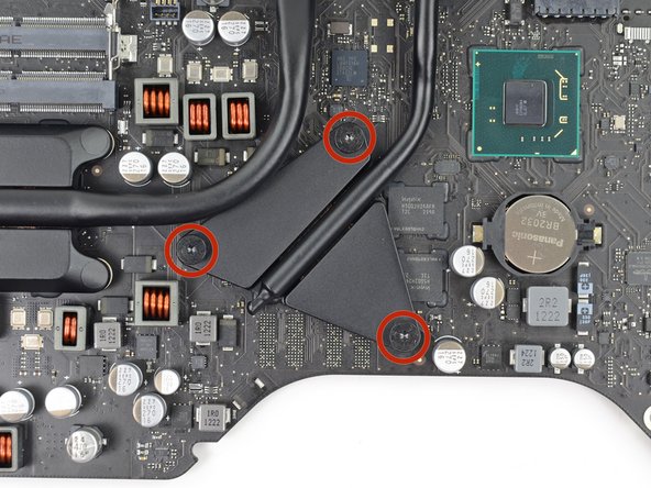
    • Remove the three 12 mm T8 Torx screws securing the GPU heat sink to the logic board.

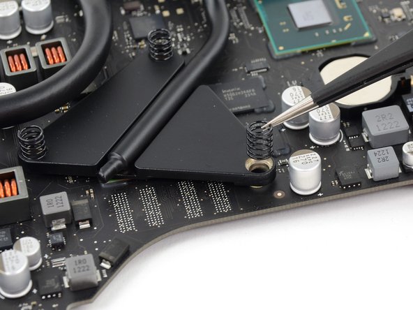
    • Remove the three springs left behind.

    • These springs might come up with the screws; be careful not to lose track of them.

  6. 이 단계는 번역되지 않았습니다. 번역을 도와주십시오

    : 6 단계, 이미지 1/2 : 6 단계, 이미지 2/2
    • Lift and remove the heat sink up off the logic board.

    • The CPU will most likely detach with the heat sink, so be careful about where you lay it down.

결승점

Sam Goldheart

회원 가입일: 10/18/12

465,826 평판

안내서 538개 작성하였습니다

iFixit iFixit 회원

Staff

135 회원들

안내서 17,161개 작성하였습니다

댓글 0개

댓글 쓰기

조회 통계:

24 시간 전: 1

7일 전: 3

30일 전: 3

전체 시간: 31