이 버전에는 잘못된 편집 사항이 있을 수 있습니다. 최신 확인된 스냅샷으로 전환하십시오.
필요한 것
-
이 단계는 번역되지 않았습니다. 번역을 도와주십시오
-
Push on each side of the left speaker cable connector with the tip of a spudger and gently "walk" it out of its socket.
-
-
이 단계는 번역되지 않았습니다. 번역을 도와주십시오
-
De-route the left speaker cable by pulling it straight up out of the retaining clip in the back of the rear enclosure.
-
-
이 단계는 번역되지 않았습니다. 번역을 도와주십시오
-
In a similar fashion as the previous step, de-route the SATA data and power cables up out of the retaining clip.
-
-
이 단계는 번역되지 않았습니다. 번역을 도와주십시오
-
Use the flat edge of a spudger to flip up the metal retaining bracket on the iSight camera cable connector.
-
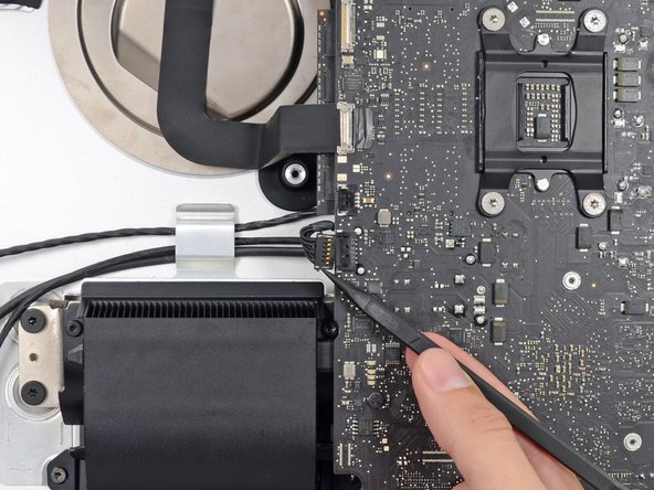
Pull the iSight camera cable straight out of its socket on the logic board.
-
-
-
이 단계는 번역되지 않았습니다. 번역을 도와주십시오
-
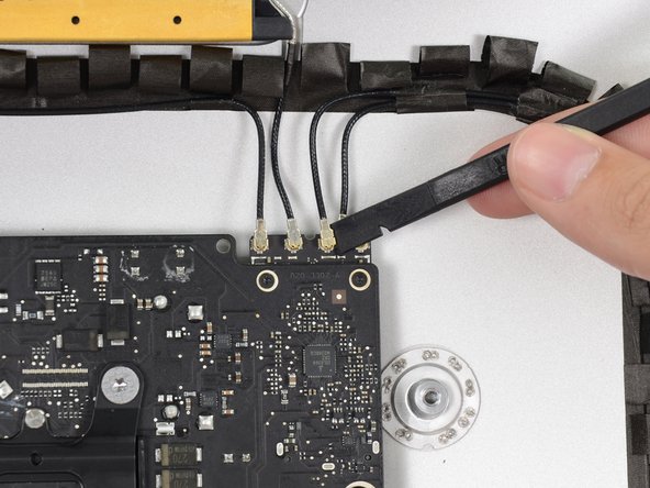
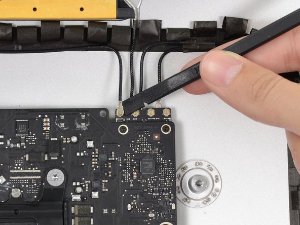
Use the flat edge of a spudger to disconnect each of the four antenna connectors from the AirPort/Bluetooth card.
-
-
이 단계는 번역되지 않았습니다. 번역을 도와주십시오
-
If brackets secure the four antenna cables, remove the two T5 Torx screws from the brackets.
-
-
이 단계는 번역되지 않았습니다. 번역을 도와주십시오
-
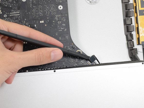
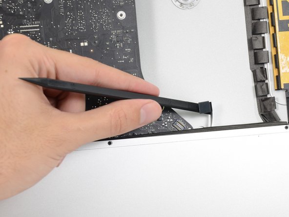
Use the flat edge of a spudger to pry the headphone jack cable connector from its socket on the logic board.
-
-
이 단계는 번역되지 않았습니다. 번역을 도와주십시오
-
Remove the following screws securing the exhaust duct to the rear enclosure:
-
Two 6.3 mm T8 screws
-
Two 4.7 mm T8 screws
-
-
이 단계는 번역되지 않았습니다. 번역을 도와주십시오
-
Remove the four 7.2 mm T10 screws securing the logic board to the rear enclosure.
-
-
이 단계는 번역되지 않았습니다. 번역을 도와주십시오
-
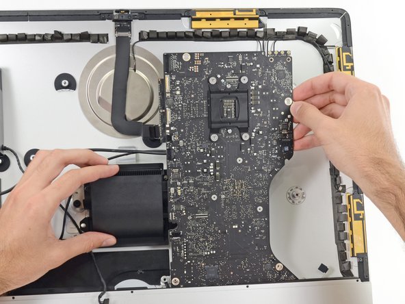
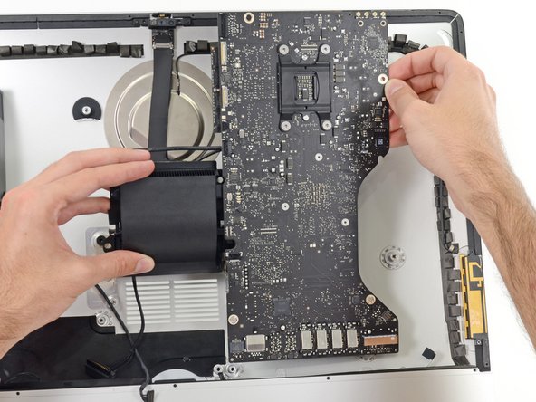
Tilt the top of the logic board away from the rear enclosure.
-
Lift the logic board straight up and out of the iMac.
-