이 버전에는 잘못된 편집 사항이 있을 수 있습니다. 최신 확인된 스냅샷으로 전환하십시오.
필요한 것
-
이 단계는 번역되지 않았습니다. 번역을 도와주십시오
-
Gently pull the left speaker cable straight out of its socket on the logic board.
-
-
이 단계는 번역되지 않았습니다. 번역을 도와주십시오
-
De-route the left speaker cable by pulling it straight up out of the retaining clip in the back of the rear enclosure.
-
-
이 단계는 번역되지 않았습니다. 번역을 도와주십시오
-
Similarly to the previous step, de-route the SATA and power cables by pulling the braid straight up out of the retaining clip.
-
-
이 단계는 번역되지 않았습니다. 번역을 도와주십시오
-
Peel up the piece of tape connecting the left speaker connector to the SATA power and data cables.
-
-
이 단계는 번역되지 않았습니다. 번역을 도와주십시오
-
Flip up the metal retaining bracket on the FaceTime camera cable connector.
-
Pull the FaceTime camera cable straight out of its socket on the logic board.
-
-
-
이 단계는 번역되지 않았습니다. 번역을 도와주십시오
-
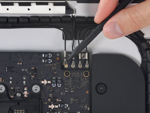
Remove the two 4.0 mm T5 Torx screws securing the four antenna connectors to the AirPort/Bluetooth card.
-
-
이 단계는 번역되지 않았습니다. 번역을 도와주십시오
-
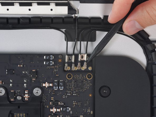
Disconnect all four antenna connectors by prying them straight up from their sockets on the AirPort/Bluetooth card.
-
-
이 단계는 번역되지 않았습니다. 번역을 도와주십시오
-
Gently pull the right speaker cable connector straight down and out of its socket on the logic board.
-
-
이 단계는 번역되지 않았습니다. 번역을 도와주십시오
-
Use the flat edge of a spudger to pry the headphone jack cable connector from its socket on the logic board.
-
-
이 단계는 번역되지 않았습니다. 번역을 도와주십시오
-
Remove the following T8 Torx screws securing the exhaust duct to the rear enclosure:
-
Two 6.2 mm screws
-
Two 4.7 mm screws
-
-
이 단계는 번역되지 않았습니다. 번역을 도와주십시오
-
Use the tip of a spudger to flip open the retaining flap on the microphone ribbon cable ZIF socket.
-
Gently pull the microphone ribbon cable straight out of its socket.
-
-
이 단계는 번역되지 않았습니다. 번역을 도와주십시오
-
Remove the four 7.3 mm T8 Torx screws securing the logic board to the rear enclosure.
-
-
이 단계는 번역되지 않았습니다. 번역을 도와주십시오
-
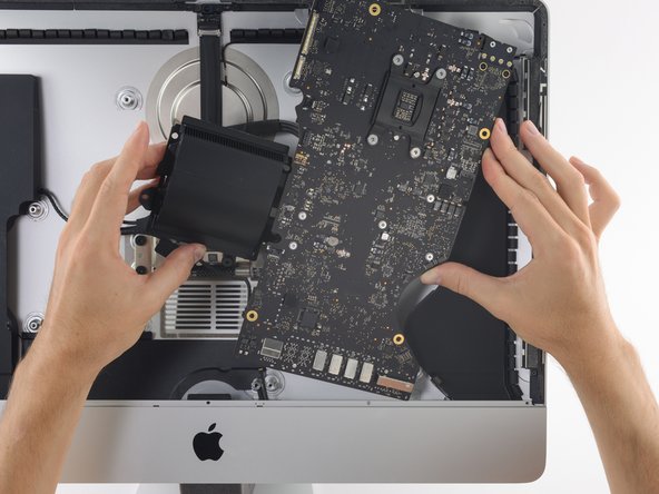
Tilt the top of the logic board away from the rear enclosure.
-
As you tilt the logic board, pull the right speaker connector to the right and out of the way of the board.
-
Lift the logic board straight up and out of the iMac.
-
-
이 단계는 번역되지 않았습니다. 번역을 도와주십시오
-
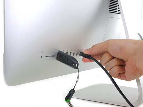
Use a USB flash drive and/or ethernet cable to keep the logic board seated correctly while you tighten the screws.
-