이 버전에는 잘못된 편집 사항이 있을 수 있습니다. 최신 확인된 스냅샷으로 전환하십시오.
필요한 것
-
이 단계는 번역되지 않았습니다. 번역을 도와주십시오
-
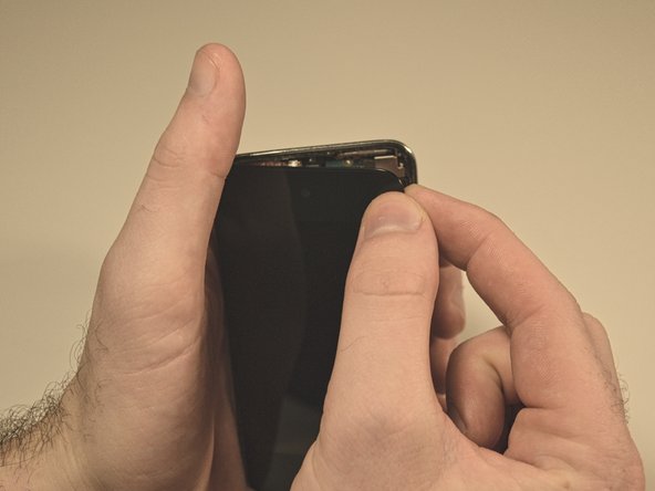
With the heat gun set on "low", begin heating the lower portion of the Touch near the home button.
-
-
이 단계는 번역되지 않았습니다. 번역을 도와주십시오
-
Insert the edge of a plastic opening tool between the front glass panel and the plastic bezel near the home button.
-
Pry the bottom edge of the front panel upward, being careful not to bend the glass excessively.
-
-
이 단계는 번역되지 않았습니다. 번역을 도와주십시오
-
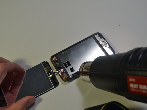
Lift the front panel away from the body of the Touch to peel up the adhesive along its left and right edges.
-
-
이 단계는 번역되지 않았습니다. 번역을 도와주십시오
-
Carefully pull the top of the front panel assembly away from the adhesive holding it to the Touch, minding the short digitizer cable connecting the two components.
-
-
이 단계는 번역되지 않았습니다. 번역을 도와주십시오
-
Remove the following eight Phillips #00 screws:
-
One 3.5 mm Phillips screw
-
Two 3.0 mm Phillips screws
-
Three 2.3 mm Phillips screw
-
One 2.4 mm Phillips screw
-
Four 2.0 mm Phillips screws
-
-
이 단계는 번역되지 않았습니다. 번역을 도와주십시오
-
Use the edge of a plastic opening tool to pry the thin steel cover up from the rear-facing camera.
-
Remove the steel cover from the iPod.
-
-
이 단계는 번역되지 않았습니다. 번역을 도와주십시오
-
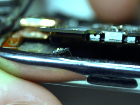
Insert the edge of a plastic opening tool under the EMI Shield near the bottom left corner of the Touch.
-
Pry upward to separate the plate from the adhesive securing it to the plastic inner case.
-
If the shield is still attached to the logic board, warm this area with a heat gun to loosen the adhesive, then separate the shield from the logic board using the opening tool.
-
There is a very thin ribbon cable here that connects the volume and power buttons to the logic board. Be careful when prying in this location as the cable is very fragile and could rip.
-
-
이 단계는 번역되지 않았습니다. 번역을 도와주십시오
-
Slightly tilt the steel EMI Shield to dislodge it from the rear case.
-
Lift the EMI shield up off the rear case and peel off the piece of copper tape stuck to the rear-facing camera.
-
-
-
이 단계는 번역되지 않았습니다. 번역을 도와주십시오
-
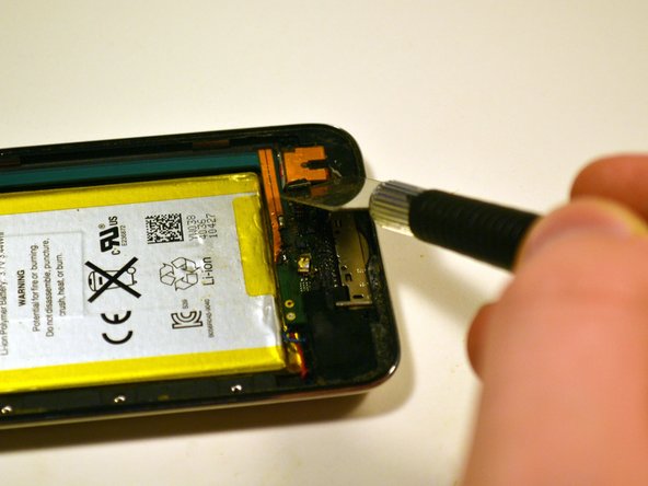
Use a plastic opening tool to pry the headphone jack connector up and out of its socket on the logic board.
-
-
이 단계는 번역되지 않았습니다. 번역을 도와주십시오
-
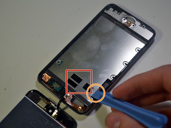
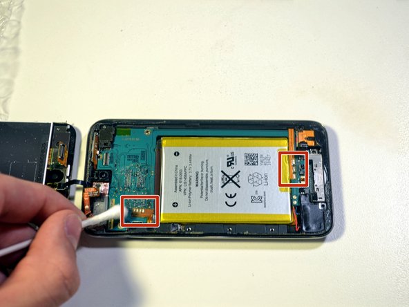
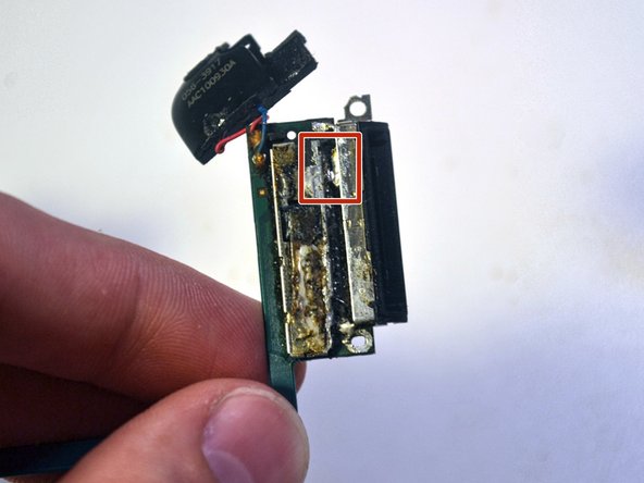
Areas highlighted in red show three solder joints to the right of the battery, along with four smaller solder joints located to the left of the battery.
-
These joints secure the power/volume flex cable (leftmost joint) and the battery flex cable (rightmost joint) to the logic board.
-
In the next few steps you will desolder the battery and power/volume flex cables from the logic board.
-
-
이 단계는 번역되지 않았습니다. 번역을 도와주십시오
-
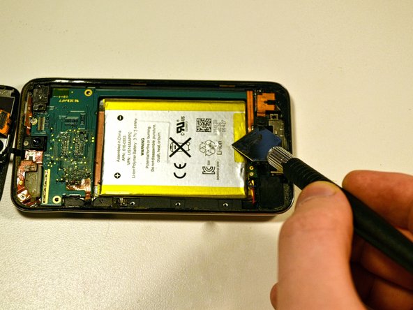
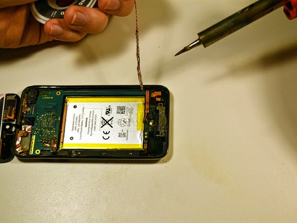
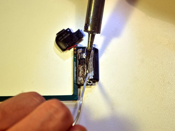
Using the heat gun, heat the silicon/glue for 5-10 seconds, then use isopropyl alcohol and a q-tip to remove the silicon/glue.
-
-
이 단계는 번역되지 않았습니다. 번역을 도와주십시오
-
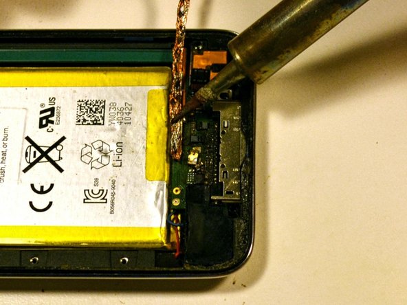
To desolder the battery flex cable, place a copper desoldering braid on top of the existing solder pads and press down on the braid with the soldering iron.
-
Once the solder melts and flows into the braid, remove the braid from the pad.
-
Repeat this process for the power/volume flex cable.
-
-
이 단계는 번역되지 않았습니다. 번역을 도와주십시오
-
Once all solder pads have been removed, gently pull both ribbon cables from the logic board and bend them back to keep them out of your way.
-
-
이 단계는 번역되지 않았습니다. 번역을 도와주십시오
-
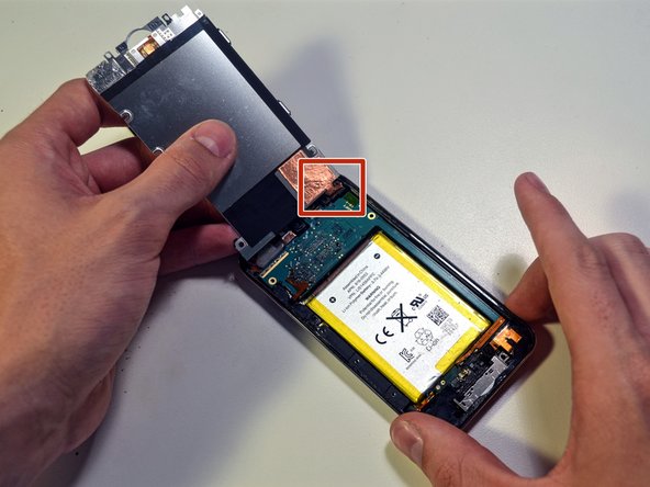
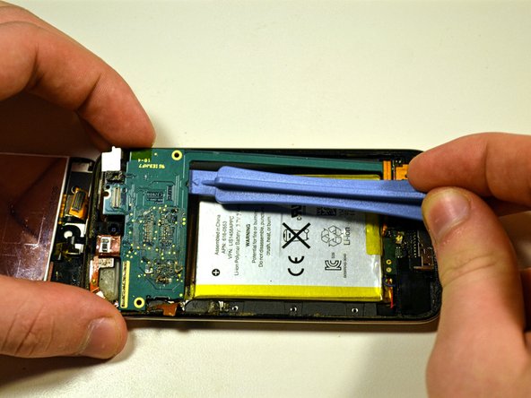
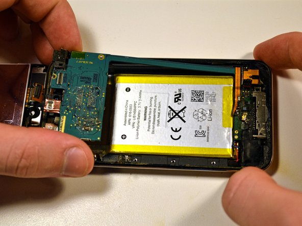
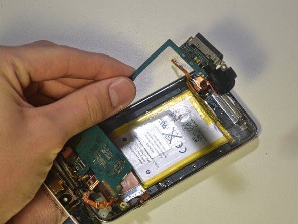
Starting above the battery near the power/volume cable attachment, use a cell phone prying tool to slowly pry the logic board straight up.
-
At this point, the top of the logic board should be lifted from the case. The bottom of the logic board and the wifi cable should still be attached to the steel housing.
-
-
이 단계는 번역되지 않았습니다. 번역을 도와주십시오
-
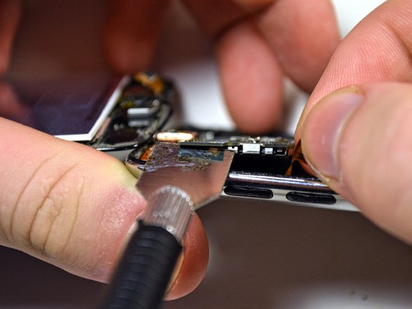
Insert the edge of a metal spudger under the logic board, between the wifi cable connector clip and the logic board.
-
Gently pry the connector from the logic board.
-
-
이 단계는 번역되지 않았습니다. 번역을 도와주십시오
-
Lightly heat the areas in red with your heat gun to soften the adhesive underneath the logic board.
-
Once heated, gently pry the logic board up with a cell phone opening tool.
-
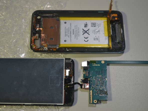
Lift the bottom of the logic board out of the casing with your fingers.
-
Remove the logic board from the steel casing.
-
-
이 단계는 번역되지 않았습니다. 번역을 도와주십시오
-
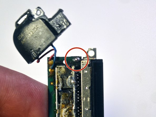
The dock connector is secured to the logic board by 30 pins and two metal joints that stick up through holes in the logic board.
-
-
이 단계는 번역되지 않았습니다. 번역을 도와주십시오
-
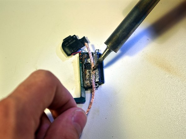
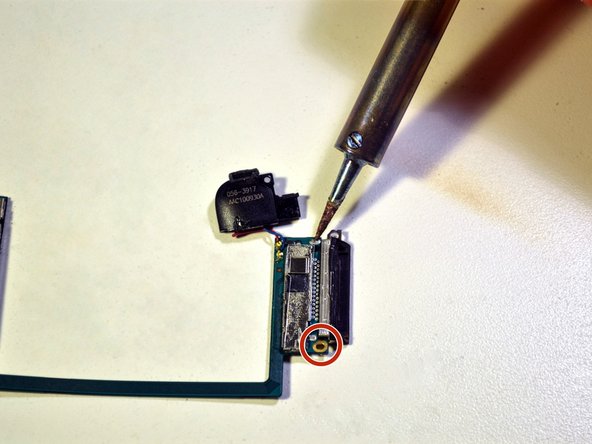
Desolder the two solder joints and the 30 pins.
-
To desolder the solder joint, place a copper desoldering braid on top of the existing solder and press down on the braid with the soldering iron.
-
Once the solder melts and flows into the braid, remove the braid from the pad.
-
Repeat this same process for the other solder joint and all 30 pins.
-
-
이 단계는 번역되지 않았습니다. 번역을 도와주십시오
-
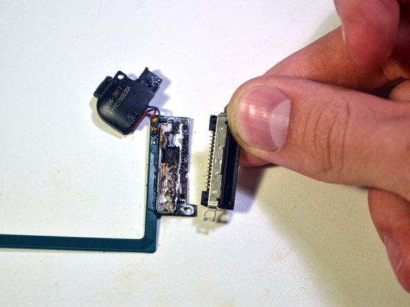
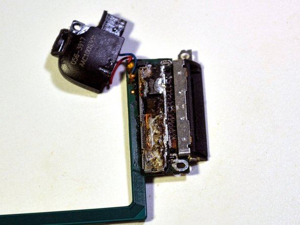
Once all solder is removed, pry the dock connector straight down from the logic board using a metal spudger.
-
If done properly, you should be able to see straight through the logic board where all 30 pins and the two metal joints used to be.
-
-
이 단계는 번역되지 않았습니다. 번역을 도와주십시오
-
With the logic board facing down, push the pins of the new connector through the holes in the logic board, making sure each pin goes through the board.
-
-
이 단계는 번역되지 않았습니다. 번역을 도와주십시오
-
Solder the two metal joints back to the logic board.
-
Place the tip of the soldering iron against the metal joint.
-
Melt solder so that it forms a dome on top of the joint.
-
Remove both the solder and the soldering iron tip from the solder pad as soon as enough solder melts onto the pad.
-
When complete, the soldered pads should have an ovular, pill like shape.
-
-
이 단계는 번역되지 않았습니다. 번역을 도와주십시오
-
Solder all 30 pins back to the logic board.
-
Heat all 30 pins with the tip of the soldering iron.
-
Melt a drop of solder onto the pins and spread it around with the tip of the soldering iron.
-
Repeat until all pins are covered in solder.
-
Remove any excess solder with desoldering braid.
-


다른 9명이 해당 안내서를 완성하였습니다.
팀

Cal Poly, Team 14-6, Green Fall 2015 Cal Poly, Team 14-6, Green Fall 2015 회원
CPSU-GREEN-F15S14G6
5 회원들
안내서 6개 작성하였습니다
댓글 4개
How do I reconnect the "display data cable"?
If I read the instructions correctly, the "display data cable" is very short and the multi-contact connector from the iTouch screen meshes with a like connector inside the iTouch. That mesh does not appear to be very secure. Are the two connectors supposed to lock or just touch? I can't tell if contact is secure and I get no display on the screen. The battery has been replaced and, I assume, charged, but I have no way to check the voltage without disassembling the unit, once again. Aside from this problem, the top of the case (screen) doesn't lock into the bottom half. Could some sealant be preventing the locking ?
If I read the instructions correctly, the "display data cable" is very short and the multi-contact connector from the iTouch screen meshes with a like connector inside the iTouch. That mesh does not appear to be very secure. Are the two connectors supposed to lock or just touch? I can't tell if contact is secure and I get no display on the screen. The battery has been replaced and, I assume, charged, but I have no way to check the voltage without disassembling the unit, once again. Aside from this problem, the top of the case (screen) doesn't lock into the bottom half. Could some sealant be preventing the locking ?